27
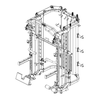
Assembly step- 5 drawing
Assembly step-5 installaon instrucon
Put sliding tube right-61 on stainless tube -right-62.
Put sliding tube -le-63 on stainless guide-le-60.
3 Assembly stainless tube -right-62 on ground tube-1 using M10*75 hexagon bolt-56,Φ10 washer-8,M10 lock
4 Assembly stainless guide-le-60 on ground tube-1 using M10*75 hexagon bolt-56,Φ10 washer-8,M10 lock
5 Assembly stainless tube -right-62 on up decorate plate-53 using M10*75 hexagon bolt-56,Φ10 washer-
6 Assembly stainless guide-le-60 on up decorate plate-53 using M10*75 hexagon bolt-56,Φ10 washer-8,M10
7 Assembly chin up bar-64 on up decorate plate-53 using M10*80 hexagon bolt-55,Φ10 washer-8,M10 lock