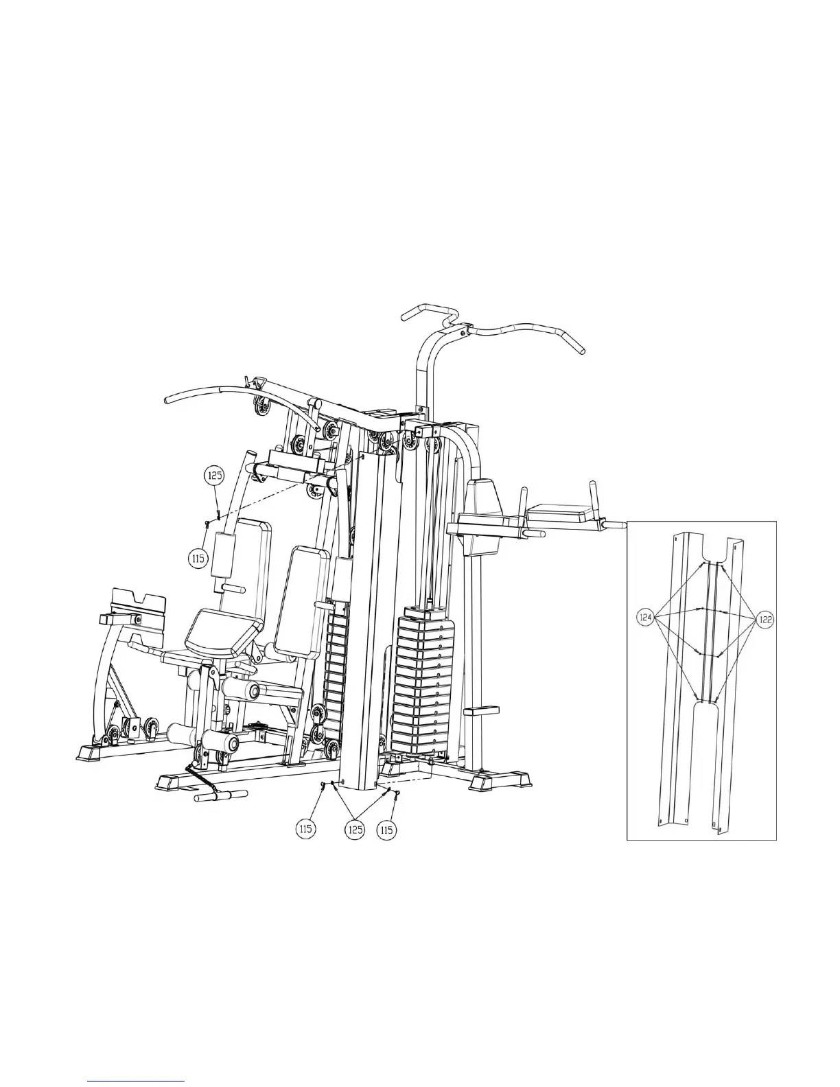
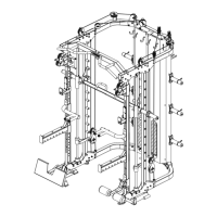
Diagram 19 (See Diagram 21)
A. Attach Left & Right Weight Stack Cage (#20 & # 21) together with four M5x10mm Philips Bolts (#122)
and M5 Aircraft Nuts (#124).
B. Attach the two weight cage assembling to the Main Base Frame (#3) and secure each of with two
M10x16mm Allen Bolts (#115) and two Ø10mm Washers (#125). And to the Left Guide Rod Holder (#6 )
with two M10x16mm Allen Bolts (#115) and two Ø10mm Washers (#125).
C. Repeat Step b to install two weight cage assembling to the Main Base Support (#3) and Right Guide
Rod Holder (#11).
Diagram 21
27


 To Next Page