CONTROLS, INSTRUMENTS AND
OPER'ATION--
22. External Check Chains
1.
Locknut
2. Turnbuckle
IMPORTANT:
When
transporting equipment
on
the
highway, it
is
recommended that a safety
chain
having a tensile strength equal
to
the
gross
weight
of
the
implement be installed between
the
tractor
and implement hitch.
See Figure
34.
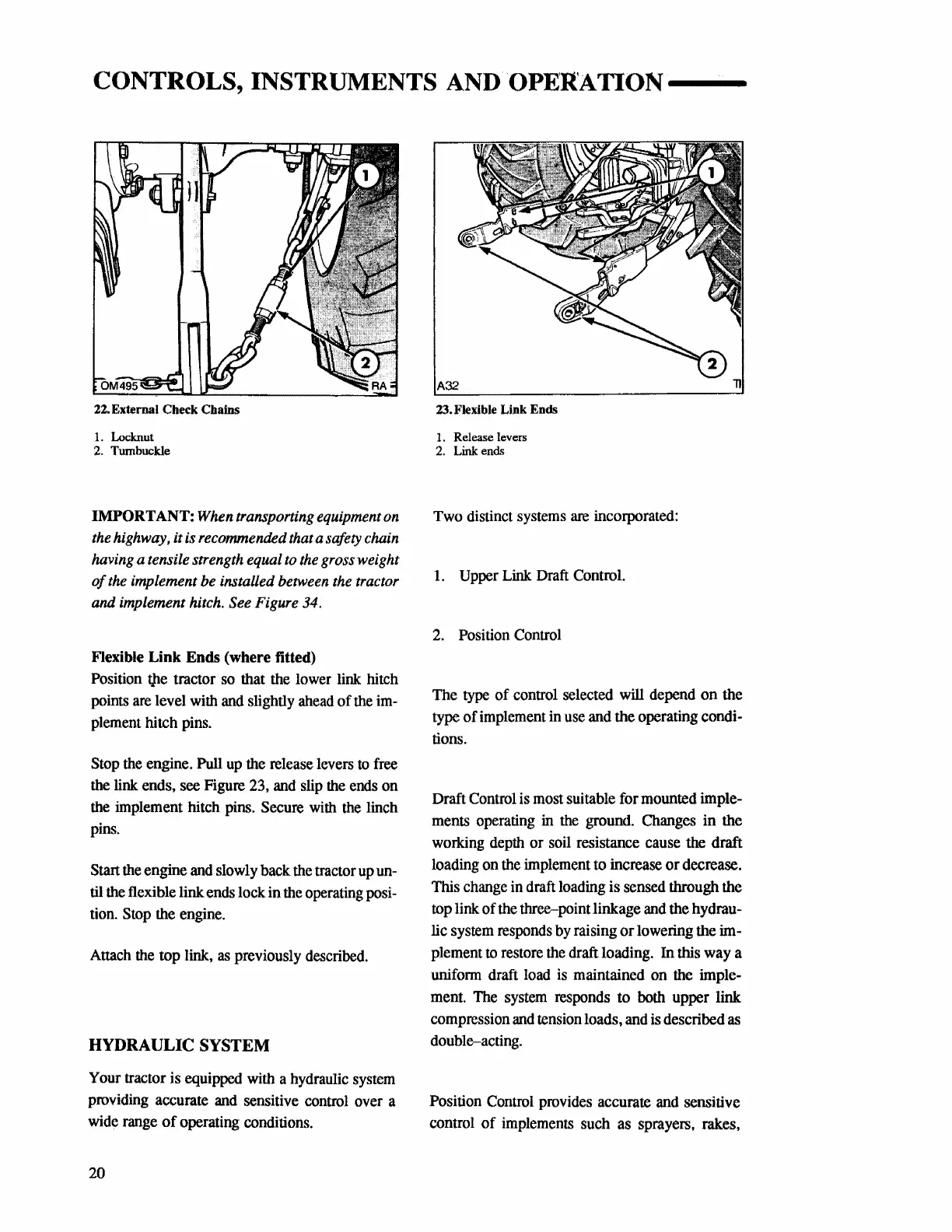
Flexible Link Ends (where titted)
Position
tJte
tractor
so
that
the
lower
link
hitch
points
are
level
with
and
slightly
ahead
of
the
im-
plement
hitch
pins.
Stop
the
engine. Pull
up
the
release
levers
to
free
the
link
ends,
see
Figure
23,
and
slip
the
ends
on
the
implement
hitch
pins.
Secure
with
the
linch
pins.
Start
the
engine
and
slowly
back
the
tractor
up
un-
til
the
flexible
link
ends
lock
in
the
operating
posi-
tion.
Stop
the
engine.
Attach
the
top
link,
as
previously
described.
HYDRAULIC SYSTEM
Your
tractor
is
equipped
with
a
hydraulic
system
providing
accurate
and
sensitive
control
over
a
wide
range
of operating
conditions.
20
A32
23. Flexible Link Ends
1. Release levers
2.
Link ends
Two
distinct
systems
are
incorporated:
I.
Upper
Link
Draft
Control.
2.
Position
Control
The
type of
control
selected
will
depend
on the
type of
implement
in
use
and
the operating condi-
tions.
Draft
Control
is
most
suitable for
mounted
imple-
ments
operating
in
the
ground.
Changes
in the
working
depth
or
soil
resistance
cause
the
draft
loading
on
the
implement
to
increase or decrease.
This
change
in
draft
loading
is
sensed
through the
top
link of
the
three-point linkage
and
the hydrau-
lic
system
responds
by
raising or lowering the
im-
plement
to
restore
the
draft
loading.
In
this
way
a
unifonn
draft
load
is
maintained
on
the
imple-
ment.
The
system
responds
to
both
upper link
compression
and
tension
loads,
and
is
described
as
double-acting.
Position
Control
provides
accurate
and
sensitive
control of
implements
such
as
sprayers, rakes,