Pinpoint Test N: The Turn Signal Indicator Is Never/Always On
Normal Operation
When the multifunction switch is in the left or the right turn position, a message is sent to the instrument cluster from the smart junction box (SJB) through the communication network, and
the left or the right turn signal indicator flashes on and off.
Possible Causes
SJB
instrument cluster
PINPOINT TEST N: THE TURN SIGNAL INDICATOR IS NEVER/ALWAYS ON
Pinpoint Test O: The Anti-Lock Brake System (ABS) Warning Indicator Is Never/Always On
Normal Operation
The status of the ABS system is sent to the instrument cluster from the ABS module over the communication network. The instrument cluster monitors the ABS input and illuminates the
ABS warning indicator when a concern is present.
Possible Causes
ABS module
instrument cluster
PINPOINT TEST O: THE ANTI-LOCK BRAKE SYSTEM (ABS) WARNING INDICATOR IS NEVER/ALWAYS ON
M4 CHECK FOR CORRECT SMART JUNCTION BOX (SJB) OPERATION
Disconnect all the SJB connectors.
Check for:
corrosion
pushed-out pins
Connect all the SJB connectors and make sure they seat correctly.
Operate the system and verify the concern is still present.
Is the concern still present?
Yes
INSTALL a new SJB. REFER to Section 419-10. TEST the system for
normal operation.
No
The system is operating correctly at this time. The concern may have
been caused by a loose or corroded connector.
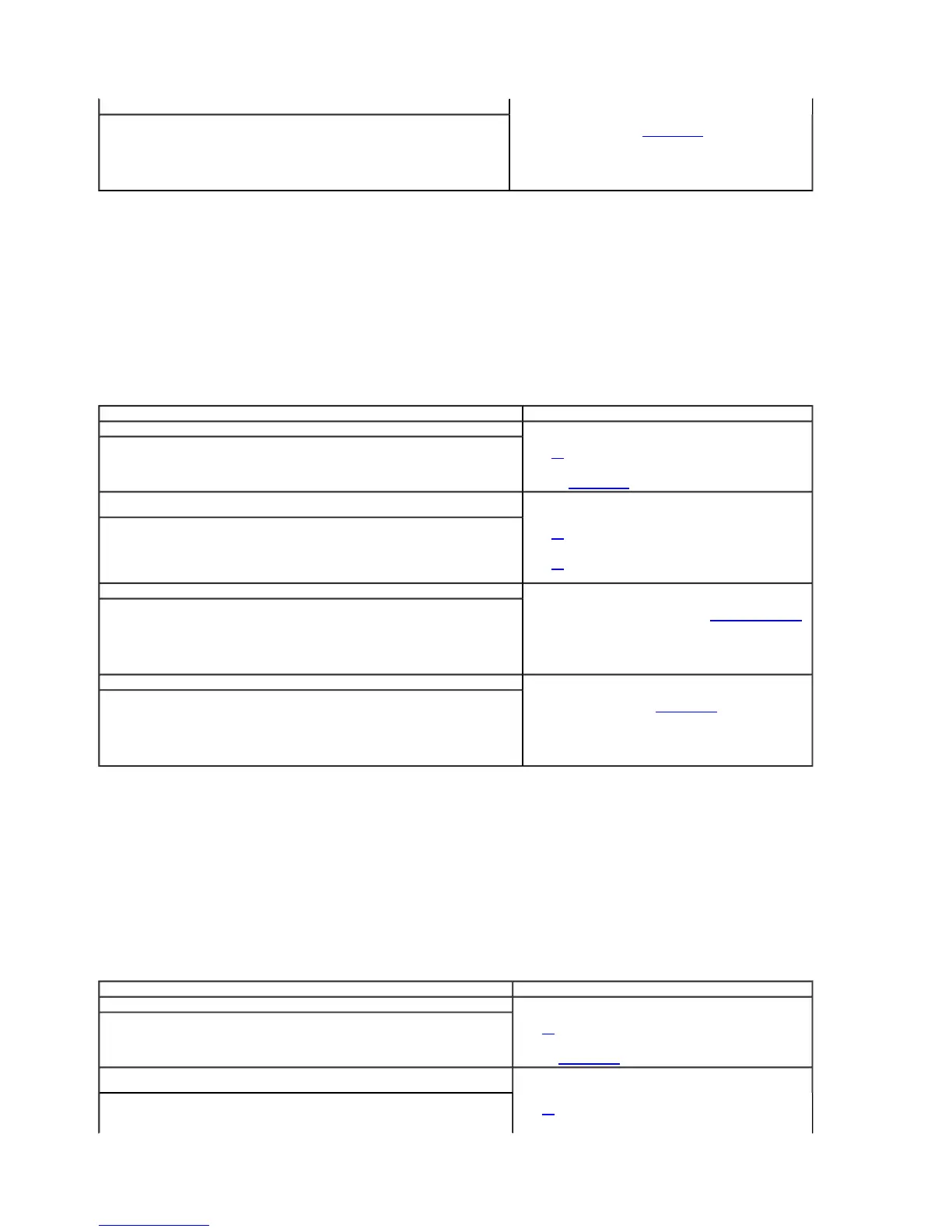
Test Step Result / Action to Take
N1 CHECK THE TURN SIGNAL LAMPS OPERATION
Ignition ON.
Operate the left and right turn signals.
Do the turn signals operate correctly?
Yes
GO to N2.
No
REFER to Section 417-01 to continue diagnosis of the turn lamps.
N2 CARRY OUT THE INSTRUMENT CLUSTER WARNING LAMPS AND CHIME ACTIVE COMMAND
USING THE DIAGNOSTIC TOOL
Ignition ON.
Enter the following diagnostic mode on the scan tool: Instrument Cluster Active Command.
Select the instrument cluster warning lamps and chime active command. Trigger the all lamps
active command on and off. Observe the LH and RH turn signal indicators.
Do the LH and RH turn signal indicators illuminate when triggered on and turn off when
triggered off?
Yes
GO to N4.
No
GO to N3.
N3 CHECK FOR CORRECT INSTRUMENT CLUSTER OPERATION
Disconnect the instrument cluster connector.
Check for:
corrosion
pushed-out pins
Connect the instrument cluster connector and make sure it seats correctly.
Operate the system and verify the concern is still present.
Is the concern still present?
Yes
INSTALL a new instrument cluster. REFER to Instrument Cluster (IC)
in this section. TEST the system for normal operation.
No
The system is operating correctly at this time. The concern may have
been caused by a loose or corroded connector.
N4 CHECK FOR CORRECT SMART JUNCTION BOX (SJB) OPERATION
Disconnect all the SJB connectors.
Check for:
corrosion
pushed-out pins
Connect all the SJB connectors and make sure they seat correctly.
Operate the system and verify the concern is still present.
Is the concern still present?
Yes
INSTALL a new SJB. REFER to Section 419-10. TEST the system for
normal operation.
No
The system is operating correctly at this time. The concern may have
been caused by a loose or corroded connector.
Test Step Result / Action to Take
O1 VERIFY THE OPERATION OF THE ABS
Road test the vehicle and verify the ABS is functioning correctly.
Is the ABS functioning correctly?
Yes
GO to O2.
No
REFER to Section 206-09 to continue diagnosis of the ABS system.
O2 CARRY OUT THE INSTRUMENT CLUSTER WARNING LAMPS AND CHIME ACTIVE
COMMAND USING THE DIAGNOSTIC TOOL
Ignition ON.
Enter the following diagnostic mode on the scan tool: Instrument Cluster Active Command.
Select the instrument cluster warning lamps and chime active command. Trigger the all lamps
Yes
GO to O3.
2005 Mustang Workshop Manual
http://www.fordtechservice.dealerconnection.com/pubs/content/

 Loading...