Pinpoint Test Z: The Anti-Theft Indicator Is Never/Always On
Normal Operation
The instrument cluster receives the anti-theft status from the PCM over the high speed CAN communication bus lines. The anti-theft indicator proves out for 3 seconds when the ignition
switch is turned to the RUN or the START position. If there is a passive anti-theft system (PATS) concern, the indicator either flashes rapidly or glows steadily (for more than 3 seconds)
when the ignition switch is turned to the RUN or START position. PATS also flashes the anti-theft indicator every 2 seconds at ignition OFF to act as a visual theft deterrent.
Possible Causes
PCM
Instrument cluster
PINPOINT TEST Z: THE ANTI-THEFT INDICATOR IS NEVER/ALWAYS ON
Test Step Result / Action to Take
Y1 CHECK THE INSTRUMENT CLUSTER VOLTAGE SUPPLY
Ignition OFF.
Disconnect: Instrument Cluster C220.
Ignition ON.
Measure the voltage between the instrument cluster, harness side and ground as
follows:
Are the voltages greater than 10 volts?
Instrument Cluster Connector-Pin Circuit
C220-3 1001 (WH/YE)
C220-25 1266 (RD/YE)
C220-26 489 (PK/BK)
Yes
GO to Y2.
No
REPAIR the circuit in question. TEST the system for normal operation.
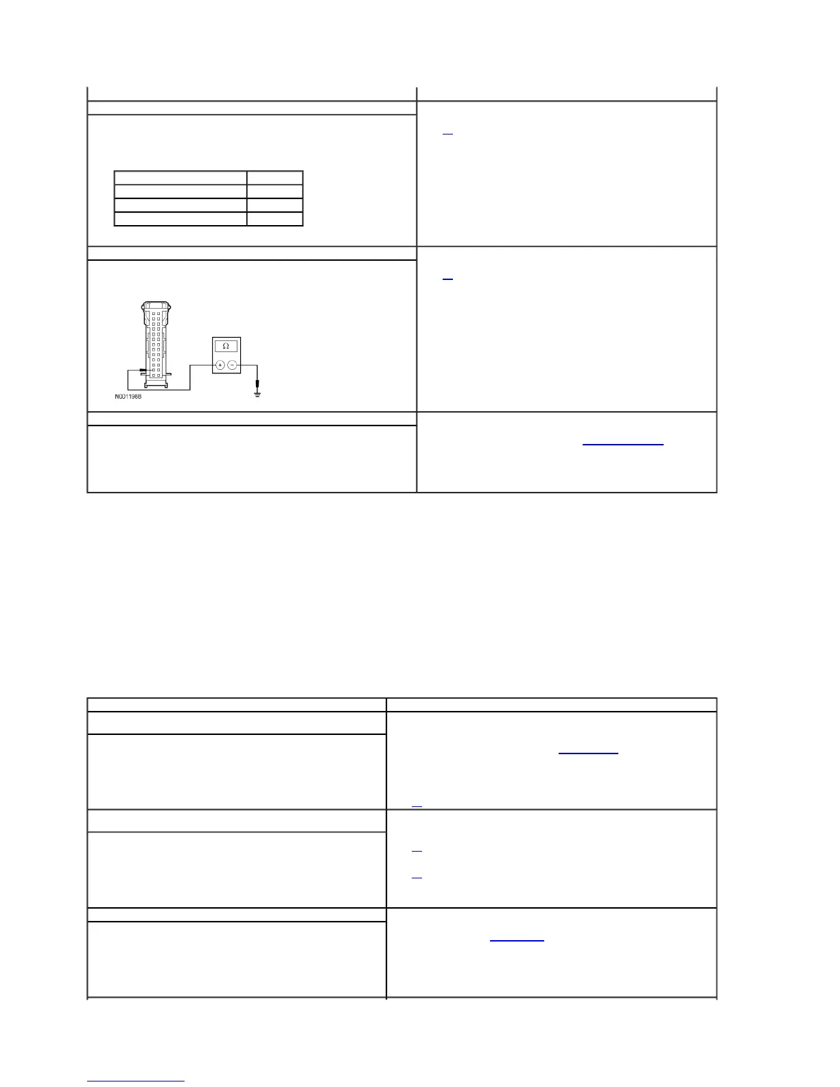
Y2 CHECK THE INSTRUMENT CLUSTER GROUND CIRCUIT
Ignition OFF.
Measure the resistance between the instrument cluster C220-2, circuit 1205 (BK)
harness side and ground.
Is the resistance less than 5 ohms?
Yes
GO to Y3.
No
REPAIR the circuit. TEST the system for normal operation.
Y3 CHECK FOR CORRECT INSTRUMENT CLUSTER OPERATION
Disconnect the instrument cluster connector.
Check for:
corrosion
pushed-out pins
Connect the instrument cluster connector and make sure it seats correctly.
Operate the system and verify the concern is still present.
Is the concern still present?
Yes
INSTALL a new instrument cluster. REFER to Instrument Cluster (IC) in this
section. TEST the system for normal operation.
No
The system is operating correctly at this time. The concern may have been caused
by a loose or corroded connector.
Test Step Result / Action to Take
Z1 RETRIEVE THE RECORDED DTCs FROM BOTH THE CONTINUOUS AND
ON-DEMAND PCM SELF-TESTS
Retrieve the recorded DTCs from the PCM continuous and on-demand self-
tests.
Are there any DTCs retrieved?
Yes
If there are any PATS DTCs present, REFER to Section 419-01B.
For all other PCM DTCs, REFER to the Powertrain Control/Emissions Diagnosis (PC/ED)
manual to continue diagnosis of the DTCs.
No
GO to Z2.
Z2 CARRY OUT THE INSTRUMENT CLUSTER INDICATOR LAMP CONTROL
ACTIVE COMMAND
Ignition ON.
Enter the following diagnostic mode on the scan tool: Instrument Cluster
Active Command.
Select the instrument cluster indicator lamp control.
Select the anti-theft indicator active command on then off again while
observing the shift indicator.
Does the anti-theft indicator turn on when commanded on and turn off
when commanded off?
Yes
GO to Z3.
No
GO to Z4.
Z3 CHECK FOR CORRECT PCM OPERATION
Disconnect all PCM connectors.
Check for:
corrosion
damaged pins
pushed-out pins
Connect all PCM connectors and make sure they seat correctly.
Operate the system and verify the concern is still present.
Is the concern still present?
Yes
INSTALL a PCM. REFER to Section 303-14. TEST the system for normal operation.
No
The system is operating correctly at this time. The concern may have been caused by a
loose or corroded connector.
2005 Mustang Workshop Manual
http://www.fordtechservice.dealerconnection.com/pubs/content/

 Loading...