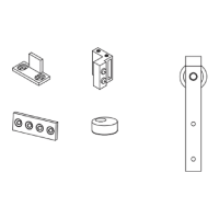
WALL
X
Y
Z
T
D
E
Rubber Bumpers
Mark the location of SIX pilot holes for the Lag Screws using a pencil, measuring tape, and
level. Use THREE Lag Scews for each Rail. Not all Rail holes will be used.
Home construction varies; holes may be added to the Rail to allow Lag Screws to attach
to wall studs. Use drill bits suitable for mild steel and a light oil such as a 3-in-1 oil to aid in
drilling. Use a
3
/32” bit for a pilot hole. Use a
7
/16” bit for the nished hole.
The holes should be located at a height from the oor 1-
5
/8” (41.5mm) greater than the door
height (H). If the oor is uneven or not level, measure from the highest point on the oor
around the door.
Proper hole location should leave a
3
/8” (9.5mm) gap under the door.
IMPORTANT
If the Rail is not installed level, the door may slide open or closed without warning.
Drill
7
/32” pilot holes to locate the Lag Screws at each mark on the wall. For any pilot hole NOT
in line with a wall stud or structural member, drill a
3
/8” hole and insert a Wall Anchor into
the hole.
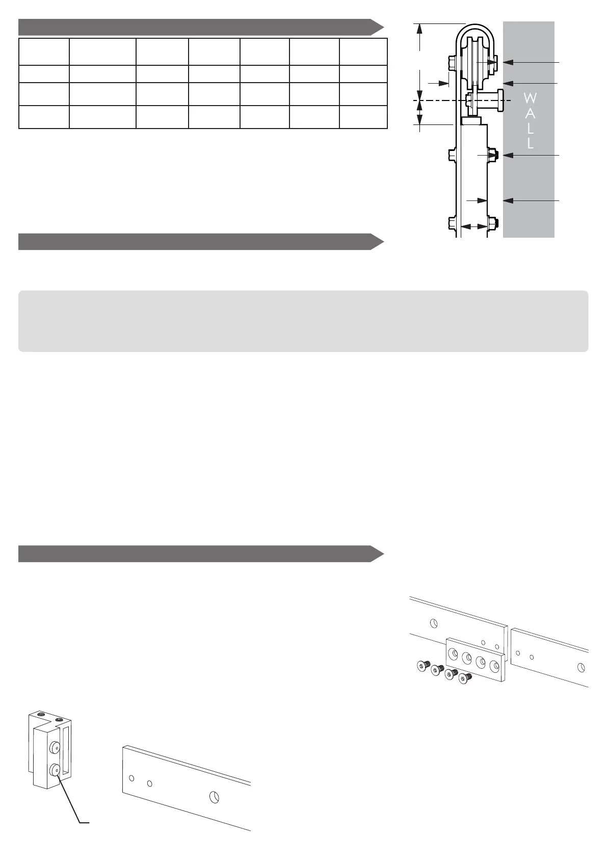
Place the two Rail parts together, so that the two small holes on each Rail are next to
each other.
2 - Assemble and Mount the Rail
Insert the Socket Head Screws through the four holes in the
Joint Plate into the Rail and nger tighten.
Making sure the top edges of the Rail are aligned, tighten the
Socket Head Screws securely.
IMPORTANT
If the Door Stops will be located between the
outermost Lag Screws, they should be placed
loose on the Rail at this time.
Loosen but do not remove the set screws in the Door
Stop and place the Door Stop with the rubber
bumpers facing the center of the Rail.
(1)
Allow at least 3/4” clearance above the trolley.
(2)
The nominal distance with the door hung to run vertical and the
wall straight and plumb. Improper installation, warped doors, extra
hardware, or decorative protrusions may reduce the clearance space.
(3)
Any additional rail and hardware mounted with a bypass bracket
system should allow this amount of space or more for proper operation
of this barn rail kit.
Door
Thickness
Trolley Top
to Rail Center
Door to
Rail Center
Bypass
Clearance
Trolley
Clearance
Bolt
Clearance
Door
Clearance
T
D
(1) (3)
E
W
(3)
X
(2)
Y
(2)
Z
(2)
1-
3
/8” 4” 1-
1
/4” 2-
7
/8”
5
/16”
1
/4”
13
/16”
1” 4” 1-
1
/4” 2-
7
/8”
5
/16”
1
/4” 1-
3
/16”
1 - Drill Holes to Mount the Rail
Planning (continued)
 Loading...