M
N
5
/16”
(Rail not shown for clarity)
M N
1-
9
/16” 5-
1
/8”
IMPORTANT
The widest part of the Spacer should be placed on the wall.
The Joint Plate should be on the side of the Rail facing away
from wall, and towards the BOTTOM of the Rail.
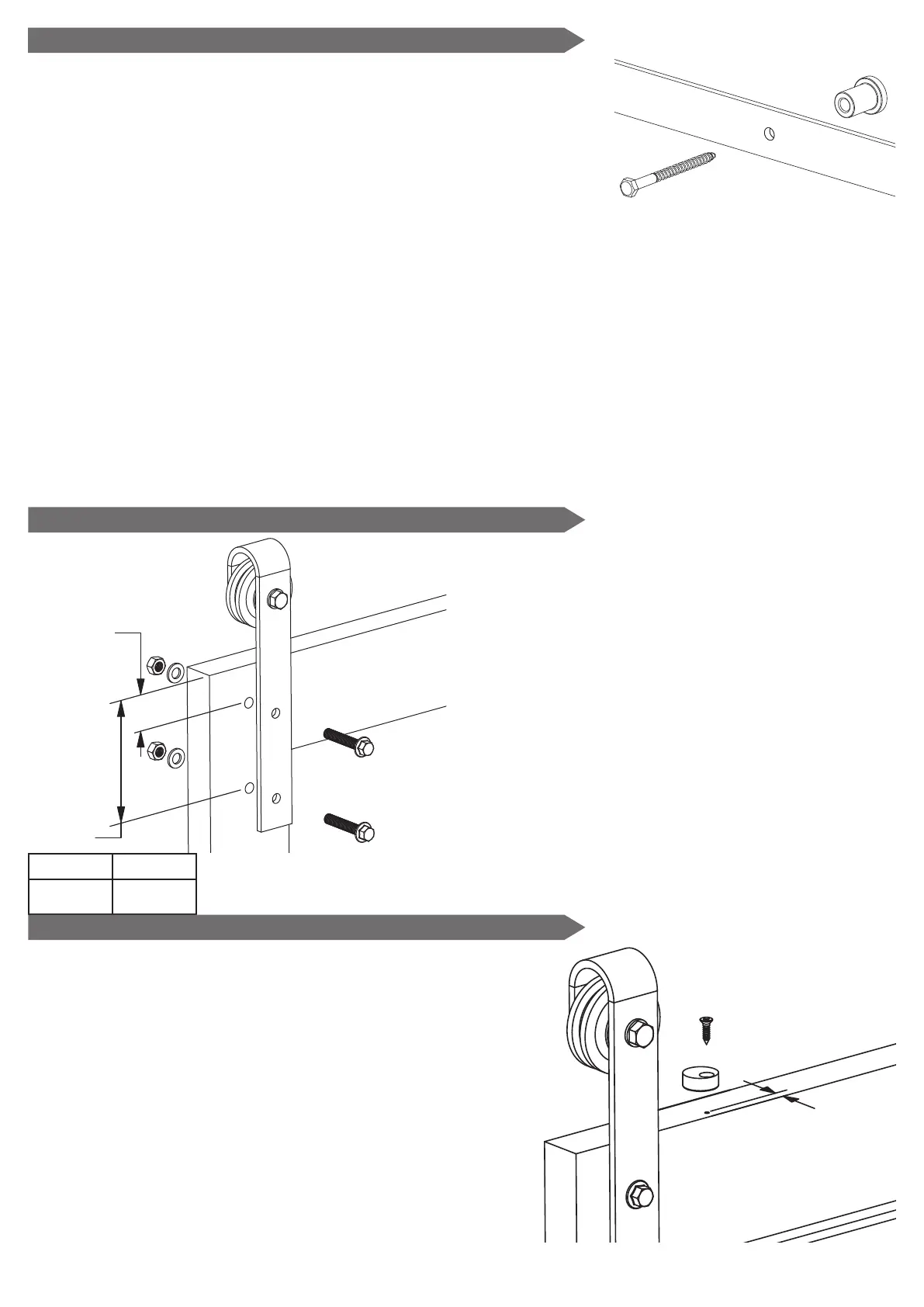
2 - Assemble and Mount the Rail (Continued)
Place a Lag Screw through the hole in the Rail aligning with the outermost pilot hole on one
side, through a Spacer, and drive the Lag Screw into the pilot hole. DO NOT fully tighten Lag
Screw.
Repeat process for a Lag Screw on the opposite end of Rail. DO NOT fully tighten Lag Screw.
Insert remaining four Lag Screws through Rail holes and Spacers, and drive into pilot holes. DO
NOT fully tighten Lag Screws.
After all Lag Screws and Spacers are in place, use a level on top of the Rail to make sure it is
properly level. While making sure the Rail is level, tighten all Lag Screws securely.
3 - Install Trolleys and Hang the Door
Mark the location of the holes for the Trolleys on
the front of the door as shown in the diagram.
Drill the holes using a
7
/16” bit.
Insert the Bolts through the Trolley and the door.
Add a Washer and Nut to each Bolt. Hand
tighten both Nuts before securing with a
wrench.
Hang the door on the Rail. Make sure both
rollers are in contact with the Rail and that the
door is level.
4 - Install Anti-Jump Pads
Drill two
3
/32” pilot holes in the top of the door and
located between and near the Trolleys, as shown
in the diagram, in order to mount the Anti-Jump
Pads.
Place the Anti-Jump Pads on the top of the door
and attach with the
3
/4” Phillips Screws.
Make sure the Anti-Jump Pad is positioned so that
the hole is towards the front side of the door and
the body of the Pad is underneath the Rail.
 Loading...