EasyManua.ls Logo

Fortin EVO KEY User Manual

Fortin EVO KEY
5 pages
To Next Page IconTo Next Page
Page #1 background imageLoading...
Page #1 background image
KEY
TUCSON
ADDENDUM - SUGGESTED WIRING CONFIGURATION
ADDENDUM - SCHÉMA DE BRANCHEMENT SUGGÉRÉ
KEY
BYPASS FIRMWARE VERSION
VERSION LOGICIELLE CONTOURNEMENT
This manual may change without notice.
www.fortinbypass.com for latest version.
Ce Guide peut faire l’objet de changement
sans préavis. www.fortinbypass.com pour la
récente version.
76.[16]
HYUNDAI/KIA MINIMUM
SEDONA
ADDENDUM - SUGGESTED WIRING CONFIGURATION
ADDENDUM - SCHÉMA DE BRANCHEMENT SUGGÉRÉ
Vehicle DATA functions supported (Functional if equipped)
Fonctions du véhicules supportés en DATA (Fonctionnelle si est équipé)
VEHICLE
VEHICULES
YEARS
ANNÉES
Immobilizer bypass
KIA
Sedona 2015
Parts required (Not included) Pièce(s) requise(s) (Non incluse(s))
1x Fuse 1X Fusible
Driver kick Panel
Panneau latéral côté chauffeur
DATA
Harnais d’ignition
Ignition harness
6
32
5
4
1
(+)Ignition
(+)12V
(+)Accessory
(+)Starter
Page 1 / 5
REV.: 20150220

Other manuals for Fortin EVO KEY

Question and Answer IconNeed help?

Do you have a question about the Fortin EVO KEY and is the answer not in the manual?

Fortin EVO KEY Specifications

General IconGeneral
BrandFortin
ModelEVO KEY
CategoryAutomobile Accessories
LanguageEnglish

Summary

Kia Sedona Wiring Addendum

Vehicle Data Functions Supported

Lists vehicle data functions supported by the module.

Installation Locations Overview

Identifies key installation points: driver kick panel and ignition switch.

Required Installation Parts

Lists parts needed for installation, not included in the kit.

Module Connectors and Pinouts

Data-Link Firmware Update Connector

Details the 4-pin connector used for firmware updates via Flash-Link Updater.

Data-Link Harness Pin Assignments

Outlines the 4-pin Data-Link connector and its pin assignments (12V, Ground, Data).

Main Harness Connections

Details the 6-pin main harness and its wire connections for ignition, key sense, and data.

Relay Harness Specifications

Specifies the 3-pin relay harness connections (NC2, NO2, COMM2).

LED Indicator Meanings

Explains the meaning of LED colors (Yellow for Ignition ON, Red for Remote Start ON).

Wiring Connection Guide

Vehicle Wiring Connections

Details wire connections to vehicle functions like ignition, starter, and door status.

Module Harness Integration

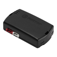
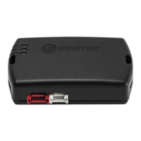
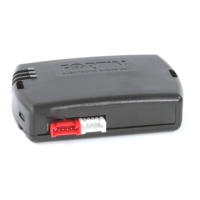
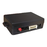
Illustrates the physical connections of the main harnesses to the module ports.

Data-Link vs. Standalone Wiring

Explains how to connect the Data-Link and power/ground wires, with/without Data-Link.

Programming Procedure

Initial Module Programming

Outlines initial steps for programming, including button presses and connector insertion.

Module Configuration Steps

Covers button presses for configuration and turning the ignition to ON/RUN.

Key Bypass Programming Completion

Details the final step for programming the key bypass and confirming module status.

Important Notices and Support

Firmware and Guide Updates Recommendation

Advises users to update firmware and download the latest installation guides from the website.

Installation Responsibility Disclaimer

States installer responsibility for verification and assumes no liability for installation accuracy.

Technical Support and Web Updates

Offers technical support contact details and website for web updates.

Related product manuals