Do you have a question about the Fostex 600 and is the answer not in the manual?
Details continuous average power output for different loads and frequencies.
Measures intermodulation distortion at rated power and mixed frequencies.
Defines the amplifier's frequency range and deviation at rated power.
Describes built-in circuits for protection against overloads and thermal issues.
Details the relay circuit protecting loudspeakers from DC or low-frequency oscillations.
Specifies the weight of the unit for shipping purposes for both models.
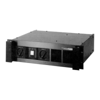
Provides the physical measurements of the amplifier chassis for both models.
Explains how to connect the amplifier for mono operation using the bridge mode.
Details speaker connection procedures for stereo operation.
Outlines speaker connection for mono operation using bridge mode.
Guides through connecting and powering on the amplifier and preamplifier.
Explains adjustment of level controls and reference points for LED indicators.
Details the procedure for adjusting bias levels using a DC voltmeter.
Outlines the steps to calibrate the front panel LED level indicators.
Lists capacitor components with their reference numbers, values, voltage, tolerance, and material.
Lists coils and transformers with reference numbers, description, and manufacturer part numbers.
Lists diodes with reference numbers, type, manufacturer, and part numbers.
Lists integrated circuits with reference numbers, type, manufacturer, and part numbers.
Lists relays with reference numbers, description, and manufacturer part numbers.
Lists switches with their description and manufacturer part numbers.
Lists transistors with type, manufacturer, part numbers, and substitutes.
Lists variable resistors with reference numbers, descriptions, and manufacturer part numbers.
Lists various non-component parts like chassis, panels, and connectors.