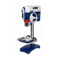
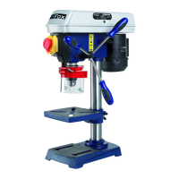
F11-991 DRILL PRESS
1. Assemble the column (A) fig. 3, to the base (B), as illustrated in the figure, with two
hexagonal headed screws which are 20 mm long (C) fig. 4.
2. Make the inferior ring slide along the column (A) fig. 26, then lock the ring by tightening
the hexagonal screw (B). Place this ring in order that the bevel of the ring can be visible
from above.
3. Slide the rack in the support of the workbench (C) in order that pinion’s teeth are in
contact with rack’s teeth (A) fig. 23
4. Make the workbench’s support complete with the workbench slide along the column until
the conic end of the rack enters the bevel of the lower ring.
5. Place the upper ring (A) on the column, in order that ring’s inner bevel blocks the upper
edge of the rack. Tighten the hexagonal screw (B) to block the upper ring fig. 25.
6. Place the head of the drill press (F) fig. 6, on the column (A) and lower it as much as you
can. After aligning the head with the workbench and the base, tighten the two screws (G)
with the wrench provided in the package.
7. Place the handwheel on the pinion fig. 7 and tighten the lock screw with the wrench for
hexagonal screw to block the handle.
8. IMPORTANT: The axle of the spindle provided separately (see fig. 24), spindle’s hole
and head’s axle hole are covered by a transparent coating against corrosion that can be
removed through a thinner. These surfaces must be cleaned in order that the spindle
correctly sticks to the axle and remains fixed during use. CAUTION: To remove the
covering you can use a home detergent, but you have to follow product’s instructions.
Then assemble the spindle (B) on the axle (A) with a sharp stroke and then, following the
same procedure, place the group axle-spindle in the conic hole in drill press’ head.
9. IMPORTANT: Open completely the jaws of the spindle by turning the ring of the spindle
(M) fig. 9.
10. Hold the spindle carefully on the axle and lock it, by striking it with a piece of wood and a
hammer, or with a mallet as illustrated in fig. 9.
11. IMPORTANT: To prevent the damage of the spindle, NEVER USE a metal hammer to
install it.
The drill press is provided with a base that grants a good stability, however, it can be fixed to a
bench with 4 screws in the holed (A) of fig. 10.
We advise you to fix it to the workbench with 4 screws by using the holes of the base (A) fig.10
in order to avoid possible risks.