17
EN
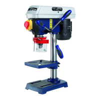
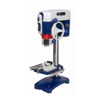
REMOVAL OF PACKAGE
Your drill press is delivered complete inside the package. Remove the
package carefully and check that nothing is missing or damaged.
In case there are any faulty or damaged parts, do not use them in order
not to compromise tool efficiency and safety. Address to an after sales
centre to replace faulty parts.
To make the drill press work perfectly you have to assemble the various
parts.
We recommend you to read carefully the assembly instructions and to
follow them to the letter.
Drill press package includes:
1.
Table support
2.
Support lock handle
3.
Column
4.
Base
5.
Support colum
n
6.
HD M8x20 he
x screw
7.
Table bevel l
ock screw
8.
Table
9.
Head
DRILL PRESS ASSEMBLY
CAUTION: FOR YOUR SAFETY, CONNECT THE DRILL PRESS TO THE POWER SUPPLY
AND SWITCH IT ON AFTER READING THIS INSTRUCTION MANUAL AND AFTER
ASSEMBLING IT COMPLETELY.
1.
Install M8x20 bolts in each hole through column support and base, and tighten with a wrench.
2.
Slide table / support into the column
.
3.
Install support lock handle from left side into table support and tighten by hand.
4.
Lift the head above the column and slide it onto the column as much as possible. Align the head with the
table and the base. Using a 4 mm hex “L” wrench, tighten the head lock set screws on the head
.
5.
Screw the feed handles into the threaded holes in the hub and tight
en.
6.
Clean out the tapered hole in the chuck. Clean the spindle nose with a clean cloth. Psh the chuck up o
n
the
spindle nose as far as possible. Lightly tap the nose of the chuck with a piece of wood to ensure
proper fitting of the chuck on the spindl
e.
7.
Install M5x12 pan screw in the hole located in guard and attach knob, turning it until it is
tighten.
8.
Choose speed for drilling operation, and install the belt in the correct position for obtaining the desid
erd
spe
ed. Loosen belt tension lock handle and turn the motor anti-clockwise to app
ly tension to the belt.
9.
Tighten belt tension lock handle.