18
EN
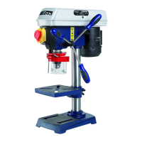
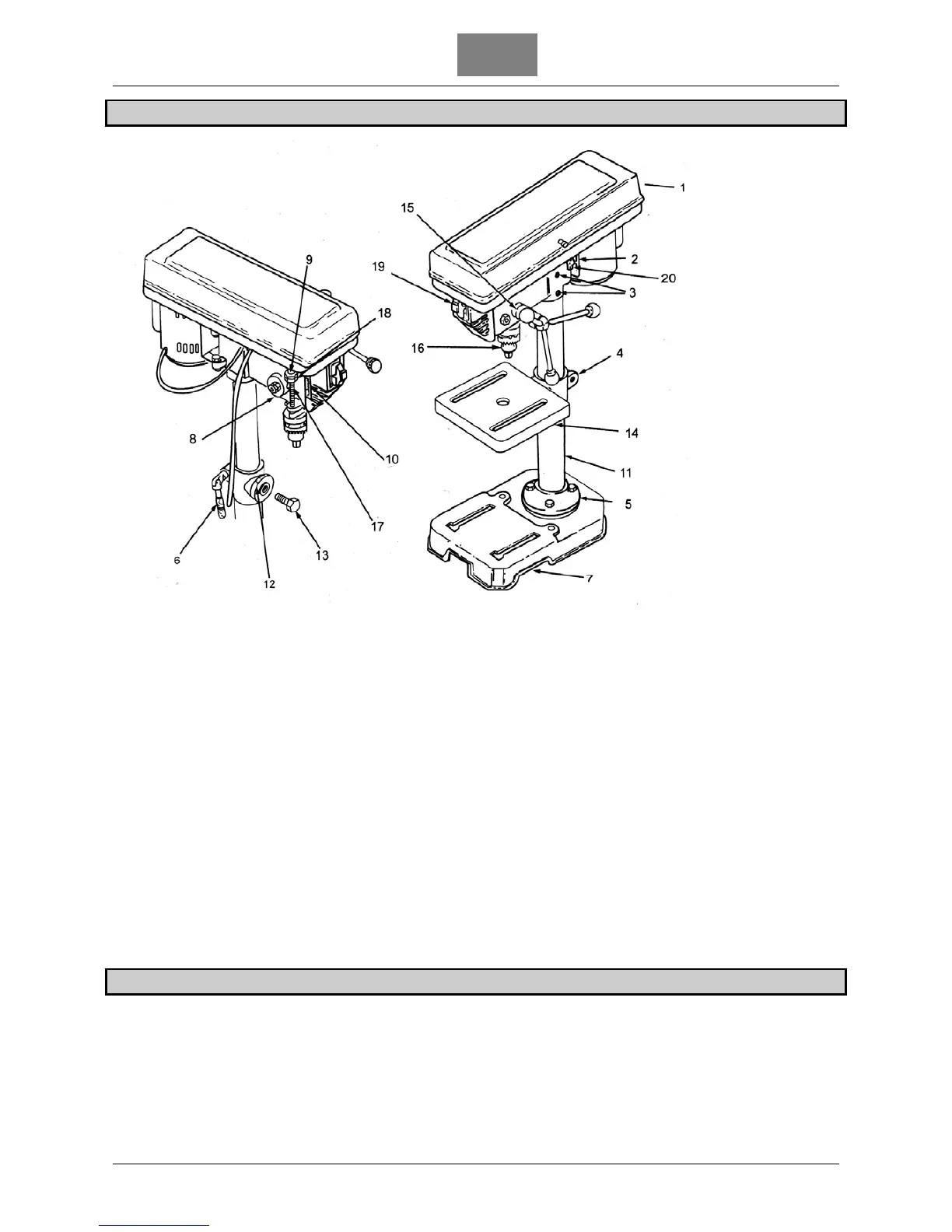
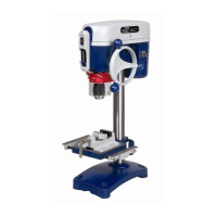
LOCATION AND FUNCTION OF CONTROLS
1. Pulley guard
2.
Belt tension lock handle
3.
Hea
d lock set screws
4.
Suppo
rt - table
5.
Column - support
6.
Suppo
rt – lock
7.
Base
8.
Spring cap
9.
Depth scale i
ndicator
10.
Depth scale
11.
Column
12.
Bevel scale
13.
Table lock se
t screws
14.
Table
15.
Feed handles
16.
Chu
ck
17.
Feed stop ro
d
18.
S
top nuts
19.
Switch
20.
Spring motor stop
DRILLING SPEED
Factors entailing better results with drill presses are the type of material, hole’s size, type of bit or miller and
cutting quality desired. The smaller the bit is, the faster the necessary speed must be. Speed must be higher
when processing soft materials than hard metals. Use the recommended speed for the bit you are using and for
the material to be cut
The chuck of this drill press can turn at 5 different speed levels: from 580 to 2650 RPM. You can obtain the
lowest speed by placing the belt on the smaller step of motor’s pulley and on the biggest of spindle’s pulley.