MACHINE INSTALLATION
Remove the protective coating from the working tables and other parts of the machine either with paraffin oil or any
similar solvent. Do not use petrol or similar solvents as they can result in reduced corrosion resistance for certain parts
of the machine.
The spindle shaper is packaged with the following parts :
Spindle ring x 18
Table ring x 2
Fence assembly x 1
22m A/F spanner x 1
Working Area
The working area size required depends on the type of machine, assumed working operations and size of material
being machined.
It is important to maintain free space of 0.8m around the machine to allow room to work. If long material is being
machined, it is necessary to have sufficient room in from the of the machine as well as behind it, where the material
enters and leaves the machine.
Ensure you leave enough space to connect a dust collector to the machine.
Connecting an Extraction System
Only use the machine with an extraction system fitted. To ensure the
proper functioning of the spindle shaper, connect an extraction system
with minimum exhaust capacity for dry particles of 570m
3
per hour and
minimum air flow of 20m/s, and for wet particles 790m
3
per hour exhaust
capacity and 28m/s minimum air flow.
Switch on the machine’s drive and extraction system at the same time.
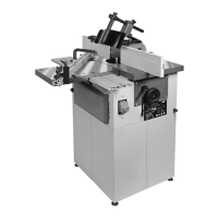
Use a flexible hose of 100mm diameter. The exhaust hose is fitted onto
the outlet from the moulding tool cover, which also forms the exhaust
connector (A). See Fig. 2.
Connecting to the mains power supply
Damaged power supply cables must be replaced by a qualified specialist immediately. Operating the machine with
damaged cables poses a serious risk of injury.
Before using the machine, ensure the voltage and frequency specified on the machine plate comply with the value of
the main supply it is connected to.
Over voltage protection should be provided by the user.
 Loading...