1
4
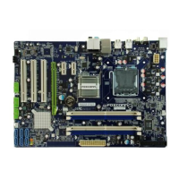
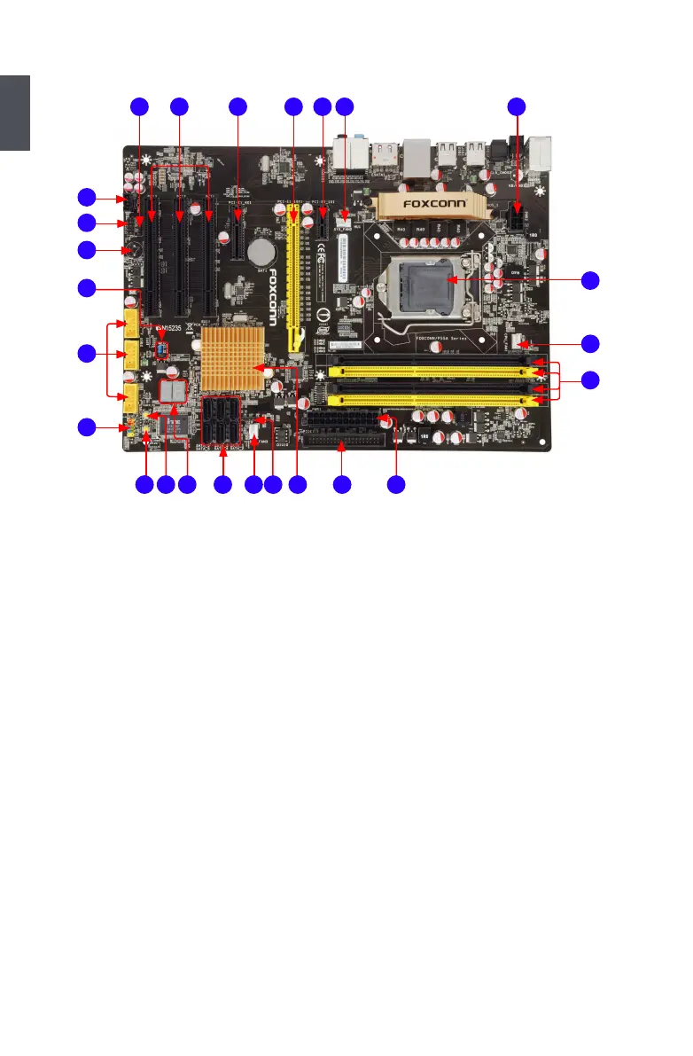
1-2 Layout
Note : The above motherboard layout is for reference only, please refer to the physical
motherboard for detail.
1. 8-pin ATX 12V Power Connector
2. SYS_FAN2 Header
3. PCI Express x1 Slot
4. PCI Express x16 Slot
5. PCI Express x4 Slot
6. PCI Slots
7. SPDIF_OUT2 Connector
8. CD_IN Connector
9. Front Audio Connector
10. Speaker connector
11. Intel® ME Jumper
12. Front USB Connectors
13. Front Panel Connector
14. Reset Button(Only for P55A-S)
15. Power On Button (Only for P55A-S)
16. Debug LED (Only for P55A-S)
17. SATA Connectors
18. SYS_FAN3 Header
19. IrDA Connector
20. Chipset: Intel
®
P55
21. IDE Connector (Only for P55A-S)
22. 24-pin ATX Power Connector
23. DDR3 DIMM Slots
24. CPU_FAN1 Header
25. LGA 1156 CPU Socket
8
9
10
11
13
12
1
25 346
7
23
24
25
21 221715 19 2016 1814