T Series User Manual www.fox-ess.com P a g e | 13
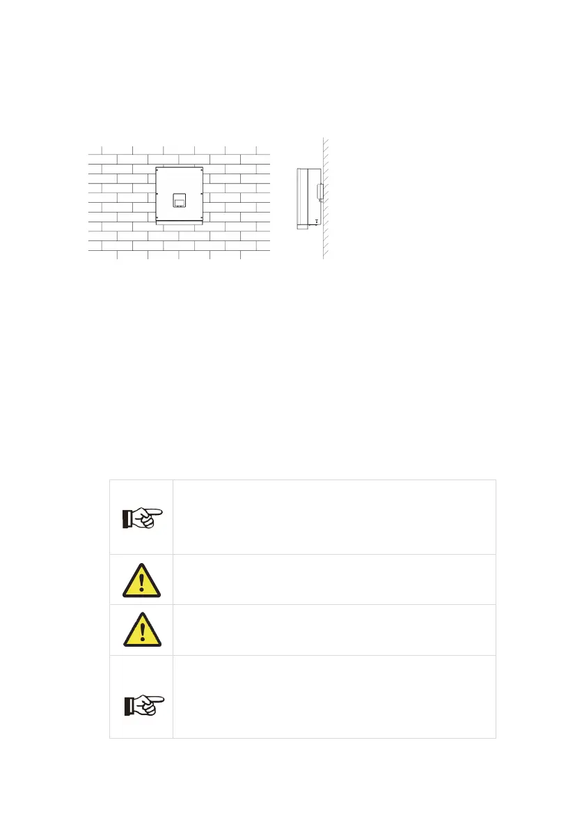
Step 2: Match the inverter with wall bracket
Hang the inverter over the bracket, slightly lower the inverter, and make sure the 2 mounting bars
on the back are properly fixed with the 2 bracket grooves.
6. Electrical Connection
6.1 Wiring Steps
Step 1: PV String Connection
T series inverters can be connected with 2 strings of PV modules. Please select suitable PV modules with high
reliability and quality. Open circuit voltage of the module array connected should be less than 1100V, and operating
voltage should be within the MPPT voltage range.
Warning!
PV module voltage is very high and within a dangerous voltage range, please comply
with the electric safety rules when connecting.
Note!
PV modules – please ensure they are the same type, have the same output and
specifications, are aligned identically, and are tilted to the same angle. In order to save
cable and reduce DC loss, we recommend installing the inverter as near to the PV
modules as possible