13
ENGLISH
RESET
LEARN
Press once Enable/Disable TAMPER signal of the selected zone
3 seconds press Reset of the selected zone
NORMAL FUNCTIONING
During normal functioning the led of the interface signalize system status as shown in the table below:
Led Z1 ÷ Z4 Description
Red At least one of the devices has generated an alarm
Orange At least one of the devices has “low battery” or “Opening tamper”
Green Normal status of the devices
OFF No device acquired
FUNCTIONING OF THE REMOTE CONTROL WL04TC
By default, the remote control keys are programmed to perform the following functions:
Button Function
Zone status indication:
System activated: 2 short beeps and 1 red blink of the led
System disabled: 3 short beeps and 1 green blink of the led
System disabling: the output is activated for 2 seconds in order to disable the system. Button
linked to the status of In3
System abling: the output is activated for 2 seconds in order to able the system. Button linked to
the status of In3
System activation or disactivation: the output is activated for 2 seconds in order to activate or
disactivate the system. This function doesn’t depend on the status of input In3
On the zone where the remote controls are acquired do not acquire different types of devices.
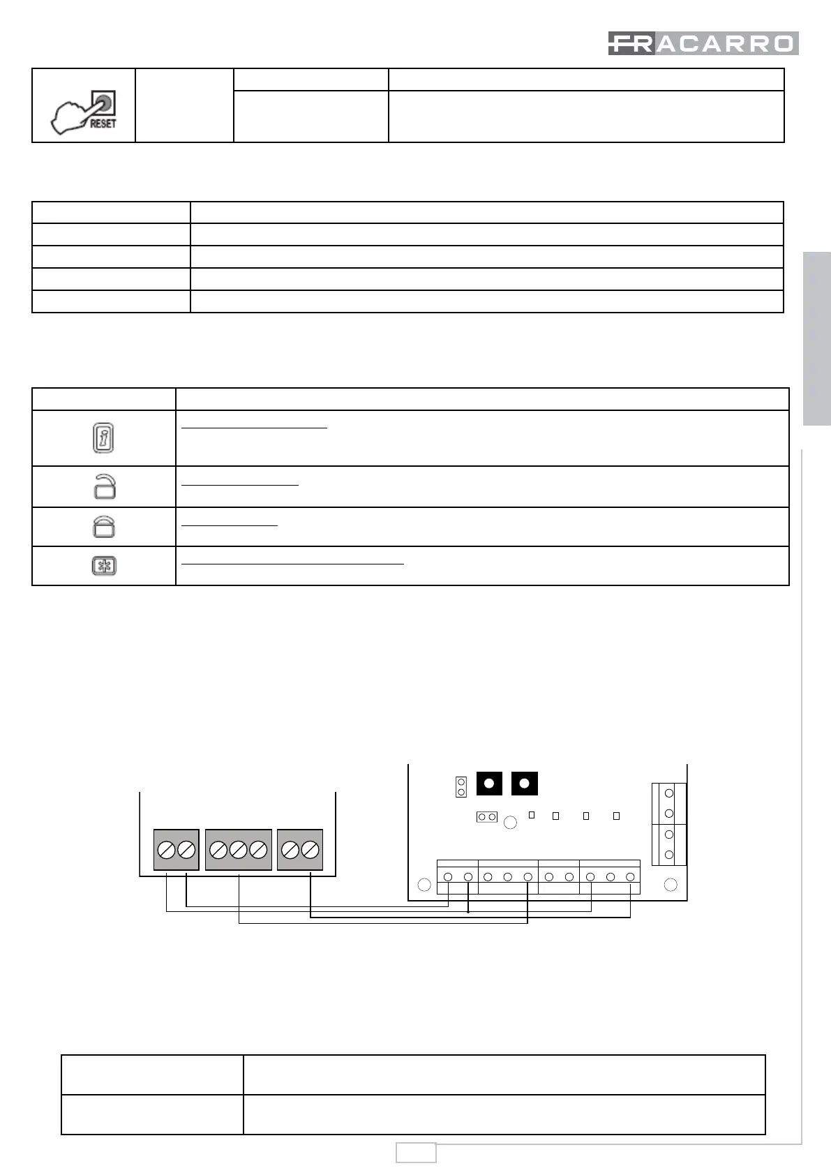
Connecting to a control panel Defender64:
To make the connection between a wired control panel and interface MOD-WL04 it is necessary to connect a cable between
the output of zone where it has been acquired a remote control (in our example, Z4) and a line of the wired control panel
where it will be programmed as line “key” type “Impulsive.”
Moreover, it will make a connection between the output “P_ON“ of the control panel and the input ”In3“ to indicate the status
of the control panel (If it is abled or disabled) which will then be displayed on the remote control WL04TC.
AC/DC In1 In2 In3 Z1 Z2 GND Z3 Z4
Jumper
MODE
Z1 Z2 Z3 Z4
LEARN RESET
OUT1
Jumper
JP
OUT2
GND
+B
ESC
P_ON
TECN
L2
L1
The output “P_ON“ must be programmed as Stable – Normally Inactive – Control panel Events: Control panel activated
Jumper JP must be Off
The output “P_ON“ is set by default as normally inactive.
To access this parameter is necessary to activate the Advanced menu of Defender 64.
Jumper JP allows the choice of recognizing the logic level of the wired control panel.
Jumper JP inserted
when with control panel deactivated there is a logical level +12V on the input In3
Jumper JP not inserted
when with control panel activated there is a logical level 0V on the input In3 (from
open-collector output)
 Loading...