13
ENGLISH
3 - INSTALLATION AND ACQUISITION
The MOD-WL16 interface can be installed within a DEFENDER control unit or as a stand-alo-
ne device within the MOD-BOX. In both cases, the connection is by Bus. NOTE: do not install
the MOD-WL16 interface within control units with metal cases.
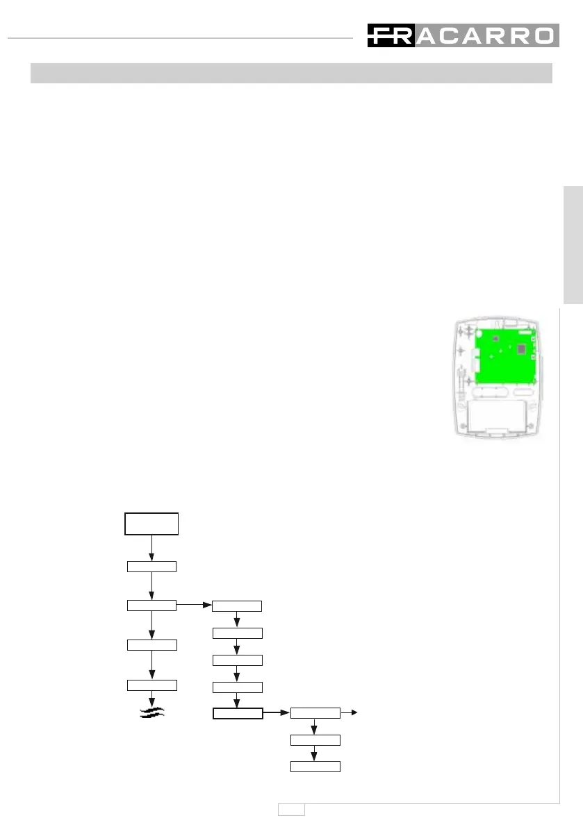
3.1- Installation within the control unit
In this type of installation, the interface is placed under the main card of the control unit.
•Removethexingscrewsofthecontrolunit’smotherboard;
•Rotatethecontrolunit’smotherboarddownwards;
•FixtheMOD-WL16tothecontrolunitbottombyusingthesuppliedscrews;
•ConnecttheinterfacetotheDEFENDERcontrolunitbythe4BUSwires;
•Fixthemotherboardtothebottomofthecontrolunit.
3.2- Installation in the MOD-BOX
This type of installation is recommended when the quality of the devices radio signals is too
weak.
•Installtheanti-tearcontact(optional)onthebottomoftheMOD-BOX
and connect it to the interface’s J2 jumper Tamper (Fig.1);
•FixtheMOD-WL16moduletotheMOD-BOXbottombyusingthe
supplied screws;
•Connectthe(optional)BT1.1(12V–1.2Ah)bufferbattery
•ConnecttheMOD-WL16unittotheDEFENDERcontrolunit’sBUS
•ClosetheMOD-BOXcoverbyusingthesuppliedscrews.
The MOD-WL16 unit can be programmed through the T8N keypad.
3.3- Acquisition of the MOD-WL16 module from the T8N keypad
The MOD-WL16 module is recognized by all the DEFENDER control units
as an auxiliary module and should therefore be acquired. Follow the flowchart to perform the
acquisition operation. Then press the ACQ/DEF key.
Control panel
Modules
Codes
Clock
Keypads
Key reader
Lines exp.module
Output
Auxiliary modules
Acquisition
Delete module
Name
Press the
ACQ/DEF key
of the module MOD-WL16
Code Installateur
000000
 Loading...