11
Location and Aeration
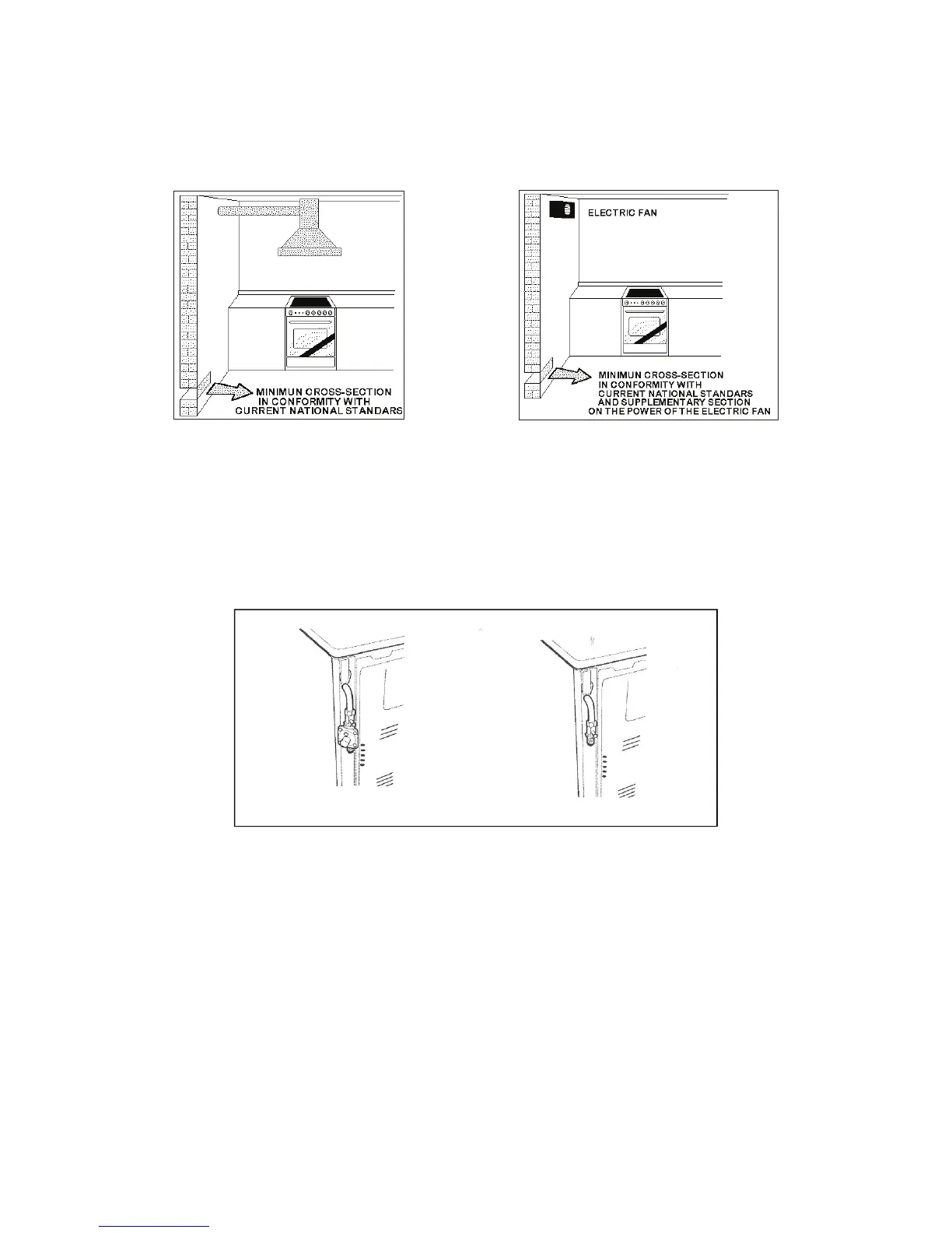
Gas cooking appliances must always evacuate the combustion products by means of hoods connected
to chimneys, flues or directly outside (Fig. 05). If a hood cannot be installed It is possible to use a fan
installed on a window or directly facing outdoors, to be operated together with the appliance ( Fig. 06),
provided that there is strict compliance with the ventilation regulations.
APPLIANCE GAS CONNECTION
IMPORTANT: This appliance must be installed by an authorised person.
WARNING: DO NOT MODIFY THIS APPLIANCE
If the appliance cannot be adjusted to perform correctly, contact the service department.
This appliance utilises a threaded 1/2” gas male fitting. To connect the appliance to the gas
network with a flexible hose, a supplemental hose nipple fitting is needed which is supplied with
the appliance. (Fig. 07)
Gas Regulator
The gas connection is via 1/2” tapered thread. Connect the cooker to the gas supply and test for
leaks. NEVER use a naked flame to check for gas leaks.
Natural Gas: Gas regulator supplied with the appliance must be installed.
ULPG: Test point adaptor to be fitted and checked at time of installation.
Fig. 05
Fig. 06
Fig. 07
Gas inlet (mm) - Nat gas
From RH rear side: 70mm
Up from floor cooker with worktop stamped: 655-725mm
Up from floor cooker with worktop welded: 675-745mm
Gas inlet (mm) - ULPG
From RH rear side: 70mm
Up from floor cooker with worktop stamped: 570-640mm
Up from floor cooker with worktop welded: 590-660mm
Gas inlet positions with different leg heights - mm