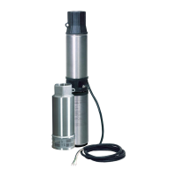
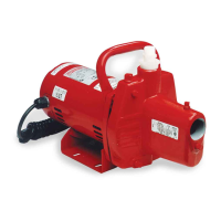
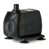
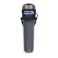
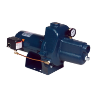
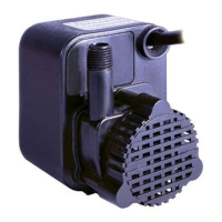
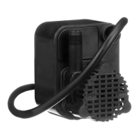
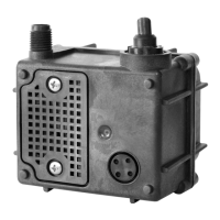
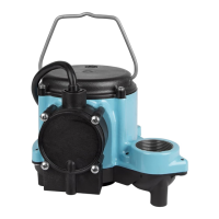
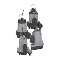
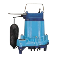
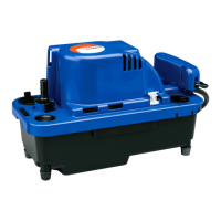
4" Environmental E-Series Pumps
OWNER'S MANUAL
English
EN
These pumps are used for filtered effluent service, aeration, and ornamental fountains or
waterfalls.
Please examine your item(s) carefully to ensure that no damage occurred during ship-
ment. If damage has occurred, please contact the place of purchase. They will assist you
in replacement or repair, if required.
This product is covered by a Limited Warranty for a period of 12 months from the date of
original purchase by the consumer. For complete warranty information, refer to
www.FranklinWater.com
.
SAFETY INSTRUCTIONS
Before Getting Started
This equipment should be installed and serviced by technically qualified personnel who
are familiar with the correct selection and use of appropriate tools, equipment, and
procedures. Failure to comply with national and local electrical and plumbing codes and within Franklin
Electric recommendations may result in electrical shock or fire hazard, unsatisfactory performance, or
equipment failure.
Know the product’s application, limitations, and potential hazards. Read and follow instructions carefully to
avoid injury and property damage. Do not disassemble or repair unit unless described in this manual.
Failure to follow installation or operation procedures and all applicable codes may result in the following
hazards:
Risk of severe injury or death by electrical shock.
• Ground motor before connecting to power supply.
• To reduce risk of electrical shock, disconnect power before working on or around the system. More than one disconnect switch
may be required to de-energize the equipment before servicing.
• Wire pump system for correct voltage. Follow wiring instructions in this manual when connecting motor to power lines.
• Check local electrical and building codes before installation. The installation must be in accordance with their regulations as well
as the most recent National Electrical Code (NEC) and the Occupational Safety and Health Act (OSHA).
• Do not use motor in swimming areas.
Risk of bodily injury, electric shock, or equipment damage.
• This equipment must not be used by children or persons with reduced physical, sensory or mental abilities, or lacking in experi-
ence and expertise, unless supervised or instructed. Children may not use the equipment, nor may they play with the unit or in
the immediate vicinity.
• Operation of this equipment requires detailed installation and operation instructions provided in this manual for use with this
product. Read entire manual before starting installation and operation. End User should receive and retain manual for future use.
Keep safety labels clean and in good condition. Keep work area clean, well-lit, and uncluttered.