Do you have a question about the FRC Turbofoam TFC200 and is the answer not in the manual?
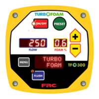
Turns the system on/off; LED indicates status.
Selects between A or B foam tanks, initiating a flush cycle.
Activates the flush or prime mode; LED indicates status.
Reports recorded incidents chronologically, with time and date.
Lists recent fault/error codes in chronological order, up to 20 entries.
Lists fault warning codes (F01-F05) related to tank levels and pump capacity.
Procedure to enter password codes for accessing programming functions.
Accesses system programming for discharge flow sensor and foam pump calibration.
Provides access to system programming for P100 codes.
Allows uploading system programming and calibration information between components.
Details P100 codes for system settings like date, time, and increment values.
Restores system programming and calibration from memory after component replacement.
Factory calibration check and procedure for installation.
Restoring calibration from memory after component replacement.
Procedure to calibrate the discharge flow sensor system.
Procedure to calibrate the foam concentrate pump and control module.
Guidelines for system maintenance after operation and routine checks.
Periodic checks for foam pump oil, components, and sensors.
Periodic maintenance tasks including oil changes and system operation checks.
Procedure to flush the system to remove foam concentrate.
Procedure to test system functionality after installation or maintenance.
Checks to perform before initiating the operational test.
Procedure to test system operation and prime the foam pump.
Flow chart and table for diagnosing system errors and faults.
A flowchart to guide troubleshooting steps for system issues.
A table listing error codes, descriptions, and probable causes.
Instructions for mounting the control module panel cutout and securing it.
Instructions for mounting the foam pump assembly and connecting cables.
Wiring details for the 12-pin and 6-pin connectors on the control module.
Wiring diagram for the foam pump control and power input.
| Brand | FRC |
|---|---|
| Model | Turbofoam TFC200 |
| Category | Control Systems |
| Language | English |