EasyManua.ls Logo

FRC Turbofoam TFC100 User Manual

FRC Turbofoam TFC100
88 pages
To Next Page IconTo Next Page
Page #1 background imageLoading...
Page #1 background image
TFC100 Rev180215
1
FIRE RESEARCH CORPORATION
www.reresearch.com
26 Southern Blvd., Nesconset, NY 11767
TEL 631.724.8888 FAX 631.360.9727 TOLL FREE 1.800.645.0074
Document Number:
XE-TFC1PM-R0A
TFC400
TFC300
TFC200
TFC100
DIRECT INJECTION
FOAM PROPORTIONING SYSTEM
WITH ELECTRIC FOAM CONCENTRATE PUMP
MODELS: TFC100, TFC200, TFC300, TFC400

Table of Contents

Question and Answer IconNeed help?

Do you have a question about the FRC Turbofoam TFC100 and is the answer not in the manual?

FRC Turbofoam TFC100 Specifications

General IconGeneral
BrandFRC
ModelTurbofoam TFC100
CategoryControl Systems
LanguageEnglish

Summary

INTRODUCTION

Overview

Describes the TurboFoam system as an automatic regulating, direct inject foam proportioning system.

System Features

Automatic Foam Proportioning

Describes the system's core function.

System Controls and Indicators

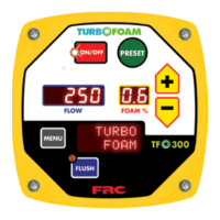
Describes buttons, LEDs, and displays.

System Components and Options

Covers tank systems, sensors, summing box, remote head, USB port.

Safety and Maintenance Features

Covers tank warnings, pressure relief, service reminders.

System Specifications

Control Module and Pump Specs

Power, current, dimensions, motor, pressure relief.

Valve and Sensor Specifications

Electric flush, ABF selector, flow sensors.

Summing Box and Pump Dimensions

Box specs and pump size dimensions.

General System Description

System Components Overview

Lists primary system parts.

Control Module and Foam Pump Assembly

Details their roles and features.

ABF Selector Valve Types

Explains manual and electric selector functions.

System Components Details

Valves and Plumbing

Electric flush valve, check valves, strainers.

Sensors and Data Input

Flow sensors, summing box, TankVision Pro, float switches.

Control and Connectivity Options

Remote control head, switches, cables.

General System Layout

Single Tank System Diagram

Illustrates TFC100/TFC200 single tank configuration.

Two Tank System Diagram

Illustrates TFC200 with manual ABF selector.

Single Tank System with Electric Flush

Illustrates TFC300 configuration.

Two Tank System with Electric ABF Selector

Illustrates TFC400 configuration.

Controls and Indicators

Button Functions

ON/OFF, PRESET, +/-, MODE, MENU buttons.

LED Indicators

Mode LEDs, FOAM EMPTY, FOAM A/B LEDs.

Display Information

FOAM % Display, FLOW Display, Message Display.

Operation and Programming

Setting System Time

Procedure for setting date and time.

System Operation

Automatic Operation Mode

How the system injects foam automatically.

Detailed Information Display

Describes message display content for TFC100 and TFC200/300/400.

Fault and Error Code Reports

Lists and explains error codes.

Incident Code Report

Describes how incident reports are displayed.

Operation Notes

Tank empty, RPM sensor loss, flow sensor loss.

Manual Mode Operation

How to enter and use manual mode.

Error Codes and Fault Warnings

Error Code Descriptions

Lists and explains system error codes.

Fault Warning Codes

Fault Warning Codes

Lists and explains fault warning codes.

Preset Settings

Accessing Preset Settings

How to set pre-programmed foam percentages.

Programming Functions

Accessing Programming Modes

Password entry, calibration, operator, restore functions.

OEM/Dealer Password Access

Restricted access for specific programming codes.

Operator P100 Codes

Key P100 Code Functions

Date/time, sensor IDs, device info, power-up settings, increments, reminders.

Set Date and Time

Setting System Date (Code P108)

Procedure to set the system date.

Setting System Time (Code P109)

Procedure to set the system time.

Set Discharge Flow Sensor ID Names

Assigning Sensor ID Names (Code P110)

How to program sensor names for summing boxes.

Set +/- Increment Value

Configuring Increment Settings (Codes P118/P119)

Setting percentage increments for adjustment buttons.

Restore Programmed Functions

Component Data Restoration

Procedures for synchronizing and restoring data between components.

Calibration, Maintenance, and Troubleshooting

Troubleshooting Flow Chart

Decision tree for diagnosing system issues.

System Calibration

Calibration Procedures and Considerations

Factory calibration, module replacement, Tank Vision Pro calibration.

Calibrate Discharge Flow Sensor

Single Sensor System Calibration

Procedure for calibrating a single flow sensor.

Multi-Sensor System Calibration

Procedure for systems with summing boxes.

Calibrate Foam Concentrate Pump

Calibration Overview and Setup

Purpose and preparation for pump calibration.

Foam Concentrate Pump Calibration Procedure

Step-by-step instructions for pump calibration.

Maintenance Recommendations

After Operation Checks

Flushing and valve position checks.

Routine Checks

Frequency and items for regular inspection.

Required Periodic Maintenance

Oil changes, system operation, calibration.

Flushing and Cleaning Procedures

Flushing, cleaning sensors and strainers.

Foam Pump Oil Maintenance

Checking and changing pump oil.

Operational Test

Pre-Operation Checks

Programming, electrical, plumbing, mechanical checks.

Performing the Operation Test

Steps to conduct the operational test.

Follow-up Calibrations

Required calibrations after the test.

Troubleshooting Guide

Troubleshooting Flow Chart

Decision tree for diagnosing system issues.

Error Codes and Fault Warnings Troubleshooting

Troubleshooting Table

Probable causes for error and fault codes.

Installation Guide

System Component Diagrams

Visual representation of plumbing.

Install Control Module

Panel Cutout and Mounting Dimensions

Specifies required panel sizes and mounting holes.

Installation Steps

System Identification and Data Input

Placards, TankVision Pro, float switches.

Switches and Plumbing Components

Remote switches, strainers, check valves, misc plumbing, flush valve.

Install Foam Pump Assembly

Pump Assembly Mounting Dimensions

Guidelines for mounting the pump assembly.

Install Manual ABF Selector

Mounting Dimensions and Connections

Specifies panel cutout and mounting hardware.

Install Electric ABF Selector

Mounting Location and Connections

Guidelines for mounting the electric selector.

Install Plumbing

Fitting Types and Configurations

NPT/BSPT threads, typical plumbing setups.

Hose Pressure and Intake Lines

Specifications for low and high-pressure lines.

Plumbing Installation Guidelines

Critical notes on sensor location, hose runs, and tank connections.

Install Discharge Check Valve Assembly

Assembly Options and Dimensions

Details check valve and flow sensor assembly dimensions.

Install Flow Sensor(s)

Flow Sensor Location Guidelines

Best practices for sensor placement for accurate measurement.

Saddle Clamp Installation

Mounting Requirements and Procedure

Steps for installing the sensor using a saddle clamp.

Weldment Installation

Mounting Requirements and Procedure

Steps for installing the sensor using a weldment.

Install Summing Box

Mounting Dimensions and LED Indicators

Guidelines for summing box installation and status lights.

System Wiring Diagrams

General Wiring Overview

Introduction to wiring schematics.

System Cables

Single Tank System Cables

Wiring diagrams for TFC100/200 single tank.

Single Tank with Flush Valve Cables

Wiring for TFC100/200/300 single tank with flush.

Two Tank System Cables (Manual ABF)

Wiring for TFC200 two tank with manual ABF.

Two Tank System Cables (Electric ABF)

Wiring for TFC400 two tank with electric ABF.

Control Module Wiring

12-Pin Connector Pinout

Description of pins on the 12-pin connector.

6-Pin Connector Pinout

Description of pins on the 6-pin connector.

Foam Pump Control Wiring

12-Pin Connector Pinout

Wiring details for the foam pump control.

DC Supply Power Input Wire Size

Recommended wire gauges for power input.

Wiring Diagrams

Electric Flush Valve Wiring

Wiring for the flush valve.

Manual ABF Selector Wiring

Wiring for the manual ABF selector.

Electric ABF Selector Wiring

Wiring for the electric ABF selector.

Remote Switch Wiring

Wiring for optional remote switches.

Optional Remote Control Module Wiring

Wiring for the optional remote module.

Sensor and Summing Box Wiring

Flow Sensor Wiring

Wiring for the flow sensor.

Summing Box Wiring

Wiring for the summing box.

Illustrated Parts Breakdown

Control Modules

TurboFoam Control Module Diagrams

Visual representation of the control modules.

Control Module Part Numbers

List of control modules and associated parts.

Cabling Diagrams

Single Tank System Cable Layouts

Diagrams for single tank systems.

Single Tank System Cable Part Numbers

List of cables for single tank systems.

Two Tank System Cable Layouts

Diagrams for two tank systems.

Two Tank System Cable Part Numbers

List of cables for two tank systems.

Foam Pump Assembly

1.6, 2.1, and 2.6 GPM Pump Diagram

Exploded view of smaller pump assemblies.

1.6, 2.1, and 2.6 GPM Pump Parts List

Part numbers for smaller pump assemblies.

3.5, 5.0, 6.2, and 6.5 GPM Pump Diagram

Exploded view of larger pump assemblies.

3.5, 5.0, 6.2, and 6.5 GPM Pump Parts List

Part numbers for larger pump assemblies.

Electric ABF Selector and Flush Valve

Component Diagrams

Visual representation of ABF selector and flush valve.

Electric Valve Part Numbers

List of electric ABF selector and flush valve parts.

Manual ABF Selector

Component Diagram

Visual representation of the manual ABF selector.

Manual ABF Selector Part Numbers

List of parts for the manual ABF selector.

Miscellaneous Plumbing Components

Component Diagrams

Visual representation of various plumbing parts.

Plumbing Component Part Numbers

List of plumbing component part numbers.

Safety and Responsibility

Personal Responsibility Code

Guidelines for user safety and responsibility.

Related product manuals