TFC100 Rev180215
41
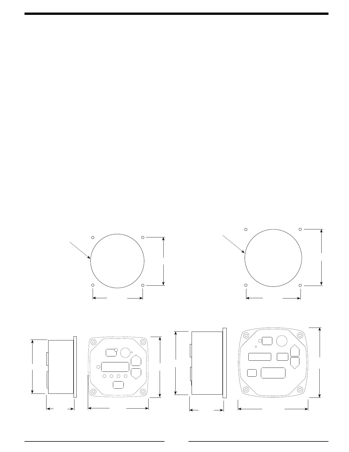
Figure L1. TFC Control Module Mounting Dimensions
INSTALLATION
After the system components are installed perform the Operational Test. (Refer to Calibration, Maintenance,
and Troubleshooting Section, Operational Test.) The ow sensor and concentrate pump must be calibrated after
the Operational Test and before normal system operations.
Install Control Module
Note: The TFC100 model requires a 3 3/4" diameter panel cutout, the TFC200/300/400 models require
a 4 3/8" diameter panel cutout.
1. Measure and mark mounting location for control module panel cutout and mounting screw holes. Make
sure there is clearance behind the panel before cutting holes. Refer to gure for layout and dimensions.
2. Cut a hole in the panel (check model and dimension) and drill four holes for 10-32 mounting screws.
3. Place the control module in position and secure with four screws.
4. Connect the cable(s) to the module. (Refer to Wiring Section.)
Note: The standard single tank control module is factory programmed for class A foam and must be
reprogrammed if used for class B foam (refer to program code P312).
Mounting holes are
clearance or tapped for
10-32 screws.
3 3/4"
Diameter
3 1/2"
3 1/2"
Panel
Cutout
4 1/4"
4 1/4"
1 7/8"
3 3/4"
4 3/8"
Diameter
3 3/4"
3 3/4"
Panel
Cutout
4 7/8"
4 7/8"
2 1/4"
4 3/8"
TFC100
TFC200/300/400
 Loading...