5
5.3. Control connections
5.3.1. Connection procedure
• remove the front panel that is secured with screws.
• for control connections use cable of 0,5 mm
2
screened
• connection cable should enter at bottom.
• connect screen to earth at the drive only .
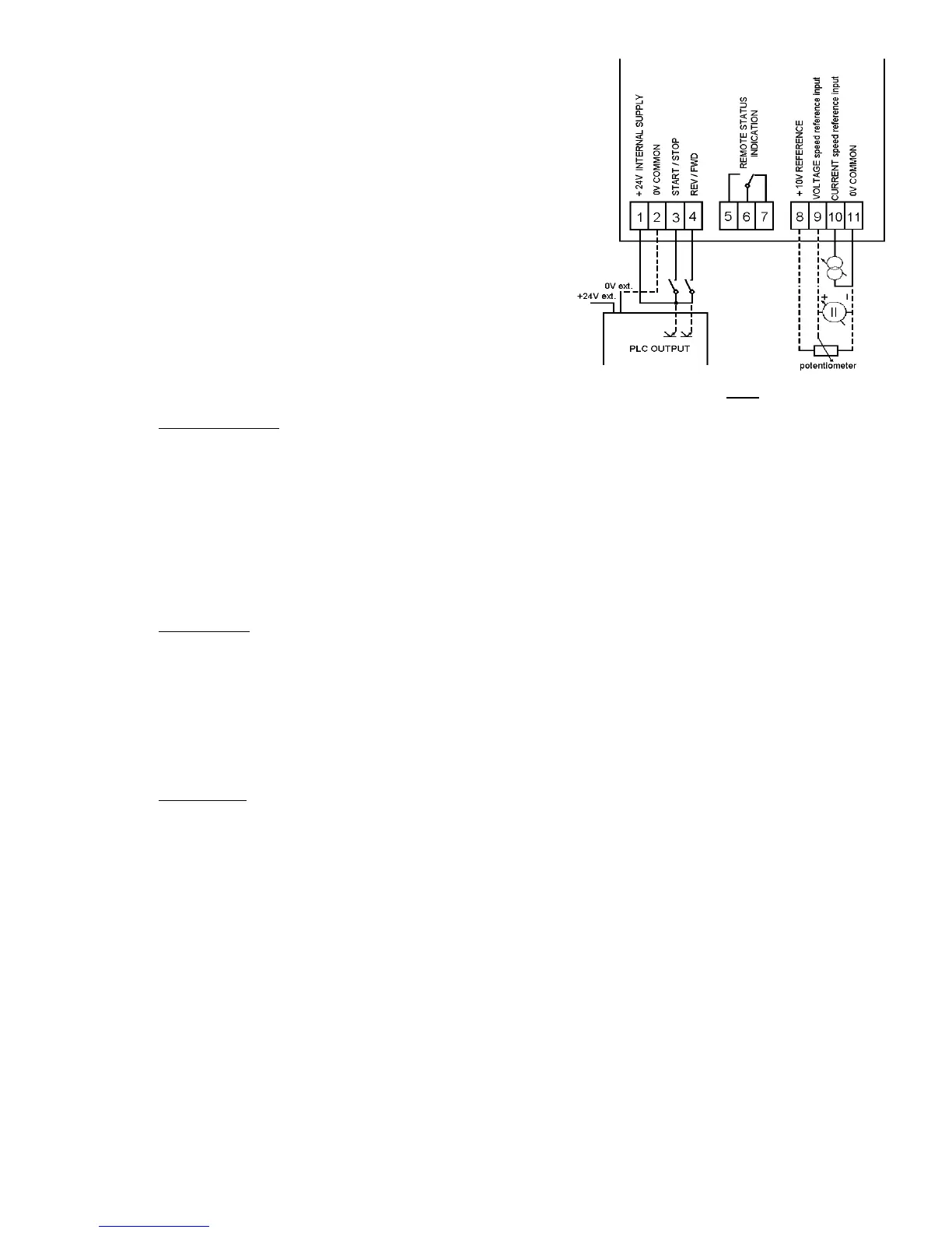
• connect control cable to terminals
(connections are shown in FIG 2).
• refit the front panel
NOTE : always segregate control and power cabling !
5.3.2. Specifications of control inputs and outputs
Complete isolation between control and power electronic circuits.
• Analogue inputs
- speed control
current input : 0 ÷ 20 mA (4 ÷ 20 mA)
120 Ω input impedance
voltage input : 0 ÷ 10 V (2 ÷ 10 V)
67 kΩ input impedance
potentiometer : 2 ÷ 20 kΩ
recommended value 10 kΩ
• Logic inputs
- run/stop : control switch or PLC output
- forward/reverse : control switch or PLC output
Input voltage : min : 15 V
DC
Input current : approx. 8,5 mA (24 V
DC
)
nominal : 24 V
DC
max : 30 V
DC
Input signal delay : max 5 ms
• Logic output
- drive status : volt-free change-over relay contact - 250 V
AC
; 8 A
6. Drive status indication
6.1. On the front panel of the drive
• LED "POWER" (red) : input voltage is present, all internal voltage levels are correct
• LED "FAILURE" (red) : internal or external trip (e.g. overvoltage, overcurrent, short-circuit ...)
the drive is stopped (disconnected from the load)
6.2. Remote indication
• Volt-free change-over relay contact
Control terminals : 5 - normally open
6 - common
7 - normally closed
Relay energised when : drive healthy
Relay de - energised when : power off or drive tripped (disconnected from the load)
FIG. 2