Appendix A Electrical Characteristics
MC9S12XE-Family Reference Manual Rev. 1.19
Freescale Semiconductor 1237
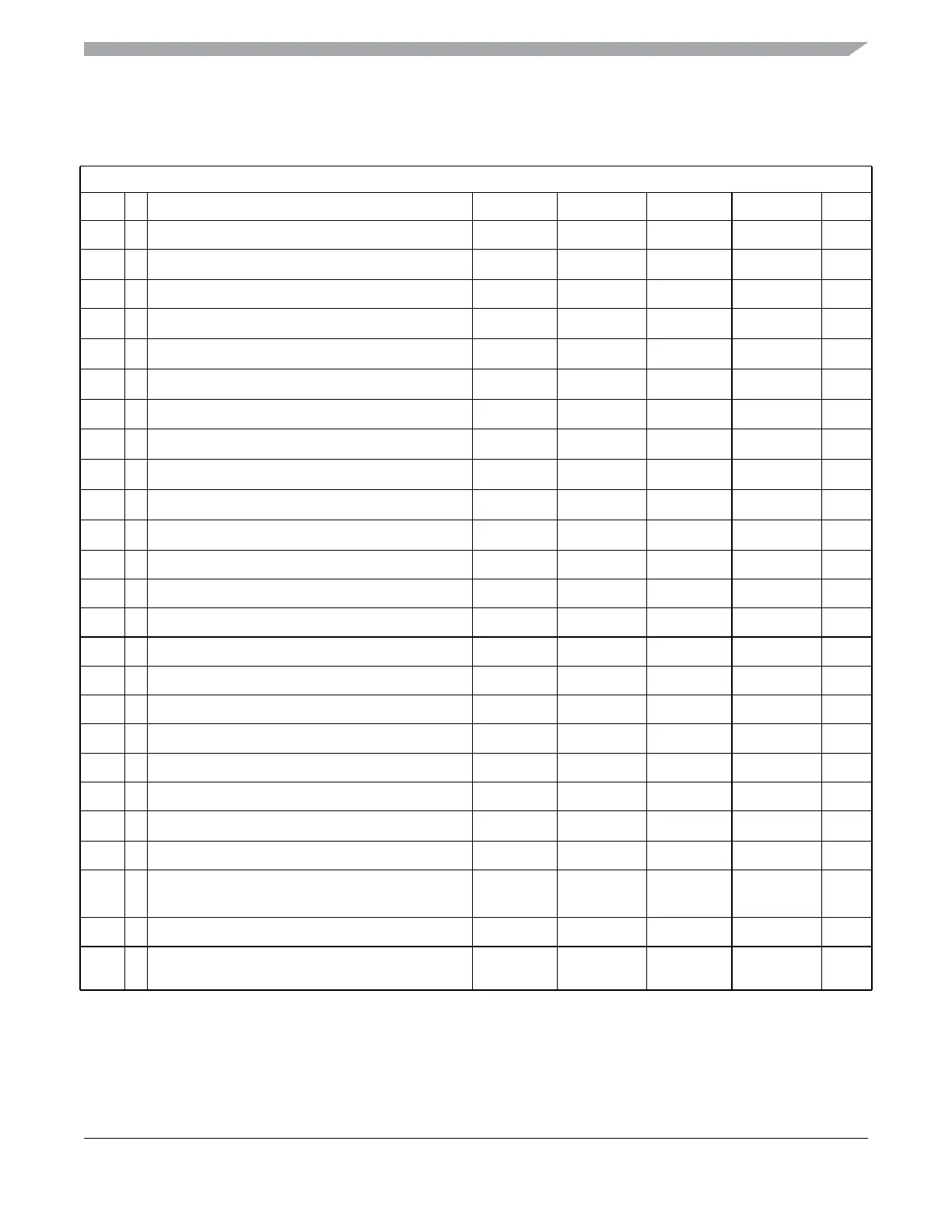
A.6.2 Oscillator
Table A-24. Oscillator Characteristics
Conditions are shown in Table A-4. unless otherwise noted
Num C Rating Symbol Min Typ Max Unit
1a C Crystal oscillator range (loop controlled Pierce)
f
OSC
4.0
—
16 MHz
1b C
Crystal oscillator range (full swing Pierce)
1,2
1
Depending on the crystal a damping series resistor might be necessary
2
Only valid if full swing Pierce oscillator/external clock mode is selected
f
OSC
2.0
—
40 MHz
2 P Startup Current
i
OSC
100
——
µA
3a C
Oscillator start-up time (LCP, 4MHz)
3
3
These values apply for carefully designed PCB layouts with capacitors that match the crystal/resonator requirements..
t
UPOSC
—
210ms
3b C
Oscillator start-up time (LCP, 8MHz)
3
t
UPOSC
—
1.6 8 ms
3c C
Oscillator start-up time (LCP, 16MHz)
3
t
UPOSC
—
15ms
4a C
Oscillator start-up time (full swing Pierce, 2MHz)
3
t
UPOSC
—
840ms
4b C
Oscillator start-up time (full swing Pierce, 4MHz)
3
t
UPOSC
—
420ms
4c C
Oscillator start-up time (full swing Pierce, 8MHz)
3
t
UPOSC
—
210ms
4d C
Oscillator start-up time (full swing Pierce, 16MHz)
3
t
UPOSC
—
15ms
4e C
Oscillator start-up time (full swing Pierce, 40MHz)
3
t
UPOSC
—
0.8 4 ms
5 D Clock Quality check time-out
t
CQOUT
0.45
—
2.5 s
6 P Clock Monitor Failure Assert Frequency
f
CMFA
200 400 1000 KHz
7 P External square wave input frequency
f
EXT
2.0
—
50 MHz
8 D External square wave pulse width low
t
EXTL
9.5
——
ns
9 D External square wave pulse width high
t
EXTH
9.5
——
ns
10 D External square wave rise time
t
EXTR
——
1ns
11 D External square wave fall time
t
EXTF
——
1ns
12 D Input Capacitance (EXTAL, XTAL pins)
C
IN
—
7
—
pF
13 P EXTAL Pin Input High Voltage
V
IH,EXTAL
0.75*V
DDPLL
——
V
T
EXTAL Pin Input High Voltage
,4
4
Only applies if EXTAL is externally driven
V
IH,EXTAL
——
V
DDPLL
+ 0.3
V
14 P EXTAL Pin Input Low Voltage
V
IL,EXTAL
— — 0.25*V
DDPLL
V
T
EXTAL Pin Input Low Voltage
,4
V
IL,EXTAL
V
SSPLL
- 0.3
——
V
15 C EXTAL Pin Input Hysteresis
V
HYS,EXTAL
—
180
—
mV
16 C
EXTAL Pin oscillation amplitude (loop controlled
Pierce)
V
PP,EXTAL
—
0.9
—
V
Because of an order from the United States International Trade Commission, BGA-packaged product lines and part numbers indicated here currently are not
available from Freescale for import or sale in the United States prior to September 2010: S12XE products in 208 MAPBGA packages