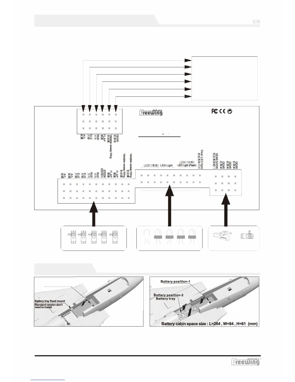
Integrated circuit module introduction
With reference to the diagram, connect the servo cables to the integrated circuit module and the receiver
correctly.
NOTE: Before flight, recheck every port on the integrated circuit panel to ensure none are loose.
In the PNP version, the cables have been factory installed and secured using a glue designed to hold them
in place to ensure integrity. If your are installing the cables, we advise using an electronic anti loosening
glue for added safety.
0
•
0
0
Servo
B
attery Installation
Battery position
/
Standard power system equipment ( One battery)
W
e rec
omm
end the
follo
wing battery si
z
e and discharge rate
:
F-14Tomcat
Receiver
0
lane
EDS
l
-
LED Light
•
0
·. Landing Gear
D
oor
S
ervo
>
Upgraded power system equipment ( Two batteries )
W
e rec
omm
end the
follo
wing battery si
z
es and discharge rates:
-10-