9. Install the filter intake pipe on the new filter. In-
stall a new O-ring on the filter intake tube, then
lubricate the O-ring with a light coat of transmis-
sion fluid.
10. Insert the filter intake pipe into the orifice on the
bottom of the transmission, then secure the filter
with the 5/16–18 x 5/8 inch washer-head cap-
screw. Tighten the capscrew 10 to 15 lbf·ft (14 to
20 N·m).
11. Place a new oil pan gasket on the oil pan. If de-
sired, a sealant may be used on the gasket, but
it must be applied carefully; sealant must be pre-
vented from contacting areas of the oil pan
flange that are inside the raised bead of the
flange.
NOTE: Do not use gasket-type sealing com-
pounds or cement anywhere inside the trans-
mission or where they might get washed into
the transmission. Non-soluble vegetable-base
cooking compounds or fibrous grease must not
be used inside the transmission.
12. Install the oil pan and gasket onto the transmis-
sion. Check that no dirt or debris enters the pan.
Secure the pan to the transmission housing with
four 5/16–18 washer-head capscrews, installed
into the corners of the oil pan, but do not tighten.
13. Install the remaining 17 washer-head capscrews
by hand. Check that all of the capscrews are
hand tight.
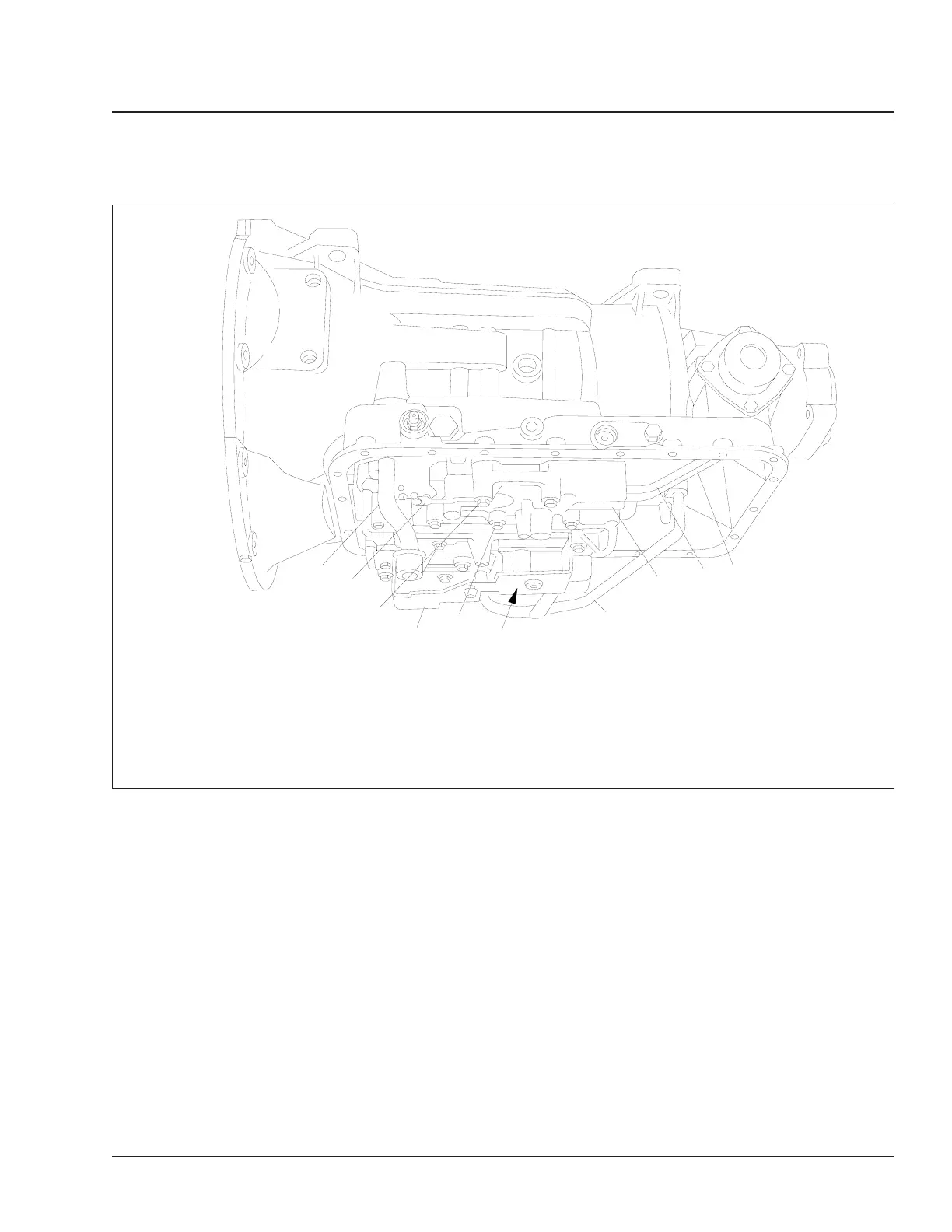
f260132a
1
2
3
4
5
6
7
8
9
10
10/05/94
1. Fluid Intake Tube
2. Detent Spring
3. Detent Spring 1-3/4" Bolt
4. Filter Spacer
5. 2-1/4" Bolt (16 qty.)
6. First/Reverse Clutch Feed Tube 3" Bolt (2 qty.,
behind)
7. First/Reverse Clutch Feed Tube
8. Governor Screen (in control valve body)
9. Governor Pressure Tube
10. Governor Feed Tube
Fig. 6, Allison AT Series Transmission Governor
Transmission 26
Business Class Trucks Maintenance Manual, February 2003 26/9