• fasteners
• frame hanger assembly
• QUICK-ALIGN connection
• shock absorbers
• torque rods
• U-beam assembly
WARNING
The pivot bushing and D-pin bushing are critical
components of the V-Ride rear air suspension. If
any components appear damaged or worn, the
component must be replaced. Failure to replace
worn or damaged components can result in the
deformation of parts, loss of clamp force, bolt fail-
ure, loss of axle alignment, loss of vehicle control,
property damage, or personal injury.
There are two types of pivot bushing inspections for
the V-Ride suspension. The pivot bushing can be
visually inspected by looking at the outer rubber
flange(s) of the bushing. If the visual inspection war-
rants, a physical inspection can be conducted in
which disassembly is required.
Pivot Bushing Visual Inspection
To perform a visual inspection of the pivot bushing, it
is not necessary to disassemble the pivot bushing
connection. If the pivot bushing rubber flange(s) are
intact and there are no signs of metal-to-metal con-
tact, the bushing does not require replacement.
• The U-beam assembly is designed with the
pivot bushings centered in each U-beam end
hub. If the pivot bushing is not centered in each
hub, it is an indication that the pivot bushing
could be worn and a pivot bushing physical in-
spection is required.
• If the pivot bushing shows signs of torn, sepa-
rated, or disconnected rubber, as shown in
Fig. 7, it could be the result of axle misalign-
ment. If this condition is evident, a pivot bushing
physical inspection is required.
• If the outer rubber flange(s) is missing, or there
are shards of rubber visible, as shown in
Fig. 7,
it could be the result of axle misalignment. If this
condition is evident, the pivot bushing must be
replaced.
Pivot Bushing Physical
Inspection
1. Remove the U-beam assembly. For instructions,
see Section 32.05, Subject 140 in the Recre-
ational Vehicle Chassis Workshop Manual.
2. After removal, inspect the pivot bushing connec-
tions and inner metal areas.
3. No replacement is needed if the pivot bushing
exhibits a tight joint. See
Fig. 8. An imprinted
two-line wear pattern on the bushing inner metal
indicates the pivot bushing is securely clamped
in the frame hanger.
4. Inspect the pivot bushing. See
Fig. 9. Any of the
following items could be the result of axle mis-
alignment or loose fasteners and require replace-
ment of the pivot bushing:
• an elongated or damaged bore
• distorted, separated, or torn rubber
• signs of rust
5. Inspect the inside of the frame hanger legs and
the QUICK-ALIGN collars. If any of the following
f32078310/05/2016
1
23
4
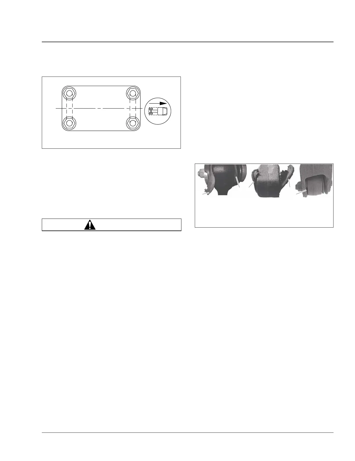
Fig. 6, Tightening Sequence for U-Bolt High Nuts
04/15/2014 f321190
1
2
1
2
3
1. Torn Rubber
2. Disconnected Rubber Flange
3. Missing Rubber Flange
Fig. 7, Inspecting for Torn, Disconnected, or Missing
Rubber Flange
Suspension 32
Recreational Vehicle Chassis Maintenance Manual, June 2015 32/7
 Loading...