formed with a long pry bar placed under each
rod end and pressure applied.
NOTE: Torque rod length is determined by the
vehicle manufacturer to center the axles under
the frame.
If the lateral alignment of the axles is incorrect,
it may be necessary to shim the torque rod end
that attaches to the V-rod bracket. See
Fig. 12.
For lateral alignment instructions, see Section
32.05, Subject 180 in the Recreational Vehicle
Chassis Workshop Manual.
3. Inspect the V-rod bracket for cracks, movement,
or damage and replace the V-rod bracket if
needed.
The torque rod may be renewed by pressing out
the worn bushings and replacing them. For in-
structions, see Section 32.05, Subjects 120 and
130 in the Recreational Vehicle Chassis Work-
shop Manual.
04/15/2014 f321194
1
2
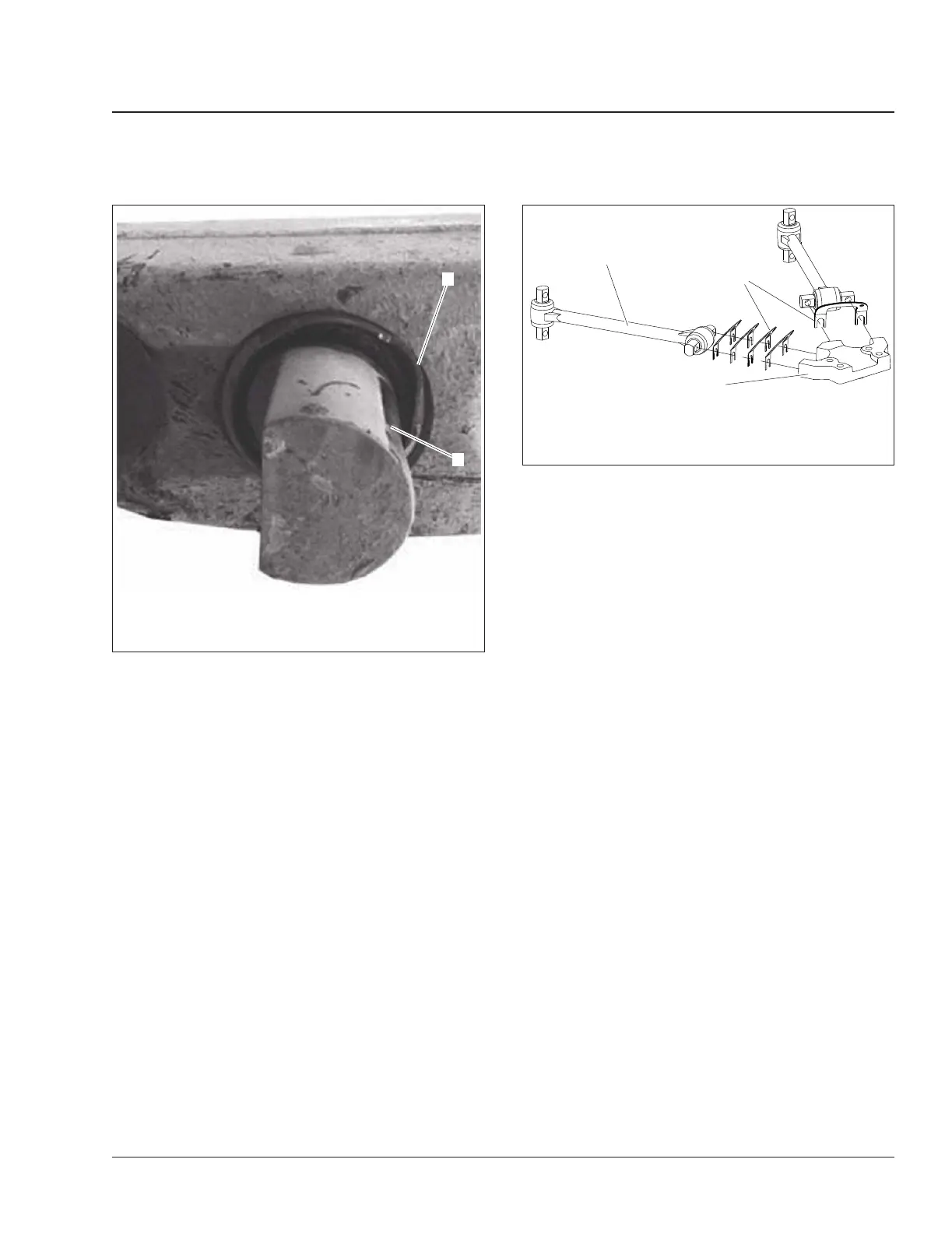
1. Distorted Outer Metal
2. Evidence of Metal-to-Metal Contact
Fig. 11, Unacceptable D-Pin
04/15/2014 f321195
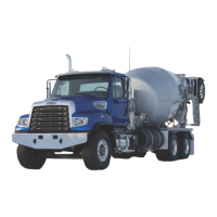
1
2
3
1. Torque Rod Assembly
2. Torque Rod Shims
3. V-Rod Bracket
Fig. 12, V-Rod Assembly
Suspension 32
Recreational Vehicle Chassis Maintenance Manual, June 2015 32/9