and Table 2 for tie-rod end clamp nut
torque specifications.
Detroit Axle Tie-Rod End Nut
Thread Torque: lbf·ft (N·m)
5/8–16 60 to 115 (81 to 156)
5/8–18 60 to 115 (81 to 156)
3/4–16 90 to 170 (122 to 230)
7/8–14 160 to 300 (217 to 407)
Table 1, Detroit Axle Tie-Rod End Nut
Detroit Axle Tie-Rod End Clamp Nut
Thread Torque: lbf·ft (N·m)
1/2–13 35 to 45 (47 to 61)
5/8–11 40 to 60 (54 to 81)
5/8–18 50 to 64 (73 to 87)
3/4–10 155 to 175 (210 to 237)
Table 2, Detroit Axle Tie-Rod End Clamp Nut
33–03 All-Axle Alignment
Checking
NOTE: The final stage manufacturer is respon-
sible for setting the vehicle ride height with air
suspension and some vehicle alignments. On
full-railed chassis, this includes the final toe-in
setting on the front axle. For modular style
chassis, both the front axle toe-in and rear axle
thrust angle settings are included.
Drive Axle Alignment Checking
NOTE: The maximum tolerance from perpen-
dicular for rear axle alignment should be ±0.25
degree.
Check the axle alignment, parallelism, and thrust
angle measurements for the rear axle. Use the appli-
cable procedure and specifications in Group 35 of
the Recreational Vehicle Chassis Workshop Manual,
or take the vehicle to an authorized Freightliner
dealer.
Toe-In Inspection
For vehicle alignment to be accurate, the shop floor
must be level in every direction. The turn plates for
the front wheels must rotate freely without friction,
and the alignment equipment must be calibrated
every three months by a qualified technician from the
equipment manufacturer. Freightliner dealers must
have proof of this calibration history.
NOTE: Toe-in should be within 0 to 1/32 inch
(0.8 mm).
1. Apply the parking brake, and chock the rear
tires.
2. Raise the front of the vehicle until the tires clear
the ground. Check that the safety stands will
support the combined weight of the body, axle,
and frame. Place safety stands under the axle.
3. Using spray paint or a piece of chalk, mark the
entire center rib of each front tire.
4. Place a scribe or pointed instrument against the
marked center rib of each tire, and turn the tires.
Hold the scribe firmly in place so that a single
straight line is scribed all the way around each
front tire.
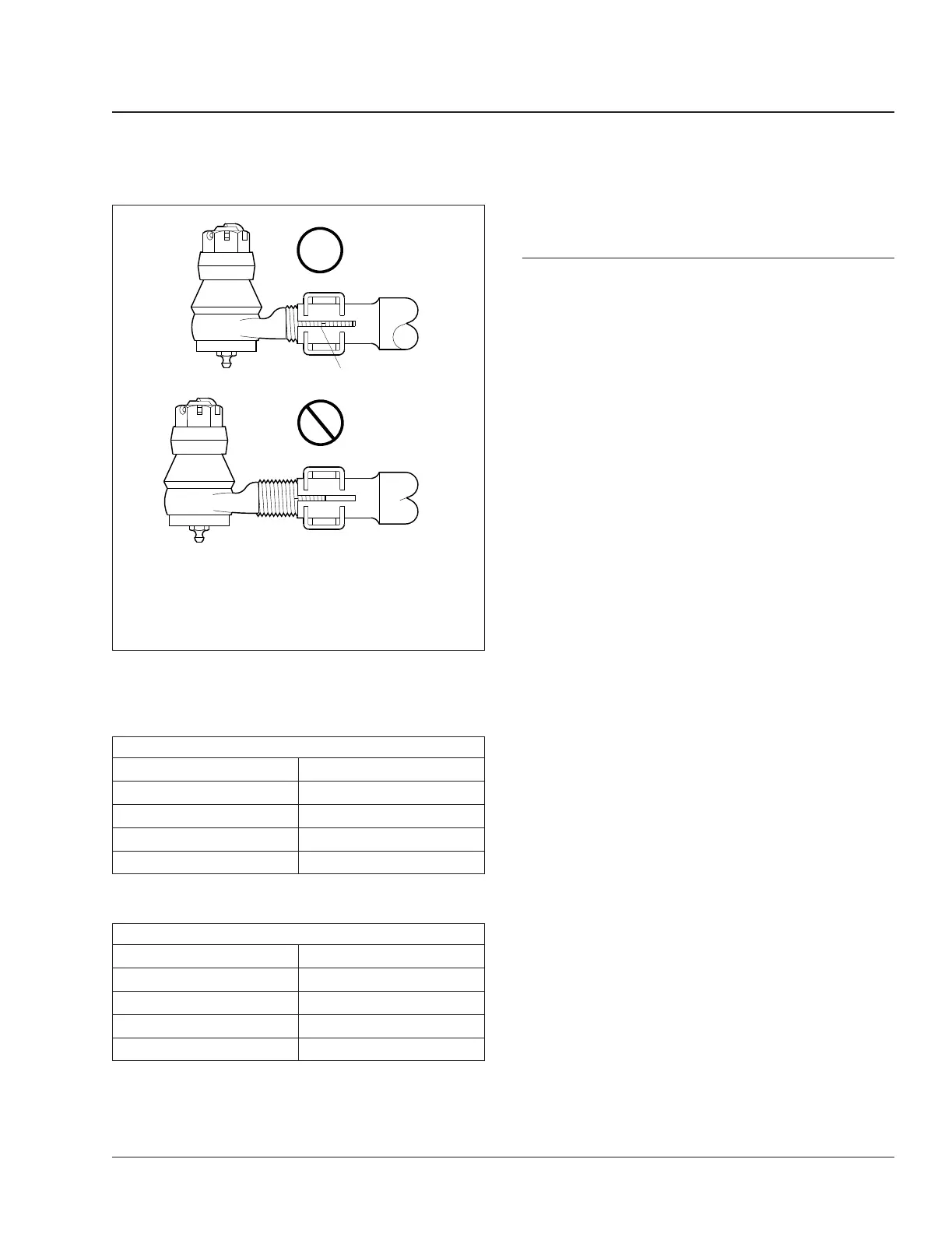
f320033a
1
OK
OK
02/27/2007
IMPORTANT: The tie-rod end threads must be visible
throughout the entire length of the split.
NOTE: Pinch bolt not shown to provide clarity.
1. Cross-Tube Split
Fig. 5, Tie-Rod End Adjustment
Front Axle 33
Recreational Vehicle Chassis Maintenance Manual, June 2015 33/3
 Loading...