QUANTUM
™
LX EVAPORATOR CONTROL PANEL
MAINTENANCE
090.610-M (MAY 2016)
Page 37
next board. Whenever a plug is not to be inserted onto
a board, either for servicing, or if not all boards are
present because of the options that are present, then a
shunting plug (refer to the Replacement Parts list) must
be installed onto the open connector.
The Analog Board requires the +5 Vdc for logic, the
-12 Vdc for internal voltage reference, and +12 Vdc for
external sensors (plus or +) and the Return (common or
-). The communications signals (RX & TX) are required
by all boards.
LOGIC VOLTAGE (POWER) LED’S
Located on the Analog Board are two power LED’s. The
rst of these is D1 LED (+5VDC), and will be illuminated
as long as the Control Power switch is ON, and the
proper voltage is present at Analog Board connector
P3. The power supply generates the +5 VDC voltage,
and passes it on through the Power-I/O harness. This
LED does not indicate however that the proper voltage
is necessarily present at the board, only that the voltage
is enough to energize the voltage sensing circuitry.
If a voltage related problem is suspected with regard to
the Analog Board, the best way to actually determine
this is to read the voltage on a DVM (Digital Volt Meter.
This may be accomplished by locating the white power
/ communications connector on the board. Notice that
the Analog Board has only one of these connectors.
The associated power / communications harness plugs
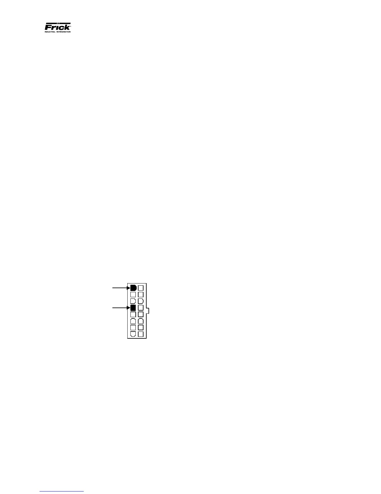
in to it. Take the red (positive) probe of the DVM and
carefully insert the end into the +5V lead, and the black
(negative) probe end into the RET (Return or Common)
lead, as shown below:
Set the DVM to read DC, and set the proper range. The
voltage reading must read a minimum of +4.98 Vdc.
The Power-I/O harness will have an associated voltage
drop at each board connection. As an example, if you
are reading the voltage at the rst I/O board in the
daisy-chain, and it reads 4.98 Vdc, you can be assured
that the voltage at the subsequent connections for
the remaining boards will be lower yet. The voltage
will need to be corrected for proper operation of the
system.
The cause for a low voltage reading could be:
• The Remote panel power supply may need
adjustment (see the section on power
supplies).
• The Power-I/O communications harness has a
problem (a new harness may be needed).
• A problem may exist with one of the I/O
boards (Digital or Analog).
• If the power LED is not lighted, check the cable
for proper connectivity. Note: Each board
provides the necessary connections to feed
all signals to the following connectors. If the
auxiliary Analog or Digital Board is not present
then a jumper plug (Part # 640B0039H01)
must be installed to daisy-chain the signals.
The second power LED is D5 (+24Vdc). This +24Vdc
voltage is generated on the Analog Board from the
+5Vdc supply being fed from the Remote panel power
supply. If the +5Vdc is present as stated earlier, then
this LED will illuminate if the on-board +24Vdc supply
is functioning properly.
ACTIVE LED
The Analog Board has an Active LED indicator that
blinks when the board’s software is running.
If the Active LED is not blinking, it could be an
indication that the internal program is not running. Try
powering the Remote panel off, then back on to see if
the Active light starts blinking. If not, a new board may
be required.
ANALOG INPUTS
An Analog Input is the portion of the hardware that allows
devices such as temperature sensors and pressure
transducers, to interface with the Quantum™ The
software program within the Quantum™ is constantly
looking at these Input channels, via communications,
and based upon what the voltage or current level of
the channel is, will provide the necessary control for
an associated action.
Analog inputs arrive at the board on connectors P4
through P10. Each of these connectors can receive two
channels (for a total of twenty-four).
ANALOG OUTPUTS
An Analog Output is the portion of the hardware that
the Quantum™ uses to provide control. These outputs
are dedicated for a 4-20 mA signal and cannot be
changed through the software conguration.
TROUBLESHOOTING THE ANALOG INPUTS AND
OUTPUTS
Some problems that may be encountered involve
troubleshooting the Analog inputs and outputs. The
Analog Board has twelve Analog I/O board connectors
labeled P4 through P10. The external Analog devices
are wired to a connector plug. Position 1 connects
to the plus (+) of the external device for channel 1,
position 2 connects to the signal (SIG) of the external
device for channel 1 and position 3 connects to ground
(GND) of the external device for channel 1. Position
4 connects to the plus (+) of the external device for
channel 2, position 5 connects to the signal (SIG) of the
external device for channel 2 and position 6 connects
 Loading...


