070.610-IOM (JUL 21)
Page 25
RWF II Rotary Screw Compressor Units
Operation
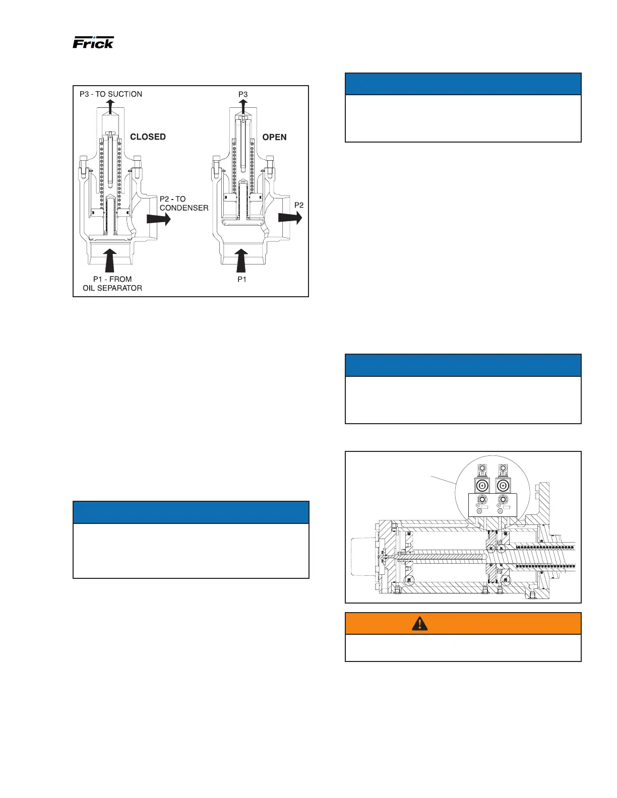
Figure 27: Cold-start valve
Compressor hydraulic system
The compressor hydraulic system moves the movable
slide valve (MSV) to load and unload the compressor. It
also moves the movable slide stop (MSS) to increase or
decrease the compressor’s volume ratio (Vi).
The hydraulic cylinder located at the inlet end of the SGC
compressor serves a dual purpose. It is separated by a
xed bulkhead into two sections. The movable slide valve
(MSV) sec tion is to the left of the bulkhead and the mov-
able slide stop (MSS) to the right. Both sections are con-
sidered double-acting hydraulic cylinders as oil pressure
moves the pistons in either direction.
Both sections are controlled by double-acting, four-way
solenoid valves which are actuated when a signal from the
appropriate micropro cessor output energizes the solenoid
valve. Valves V1, V2, SC1, SC3, and SC4 are always open.
NOTICE
The solenoid coils can be serviced or replaced with-
out evacuating the package. However, if the hydraulic
solenoid valves or manifold block needs to be serviced
or replaced, then the compressor package must be
evacuated.
Single-acting mode - high stage
Close valve at SC2
Open valve at BP (bypass)
High stage compressor loading: The compressor loads
when MSV solenoid YY2 is energized and oil ows from
the unload side of the cylinder out port SC1, through valve
ports A and T to compressor suction. Simultaneously,
discharge pressure loads the slide valve.
High stage compressor unloading: The compressor
unloads when MSV solenoid YY1 is energized and oil
ows from the oil manifold through valve ports P and A to
cylinder port SC1 and enters the unload side of the cylin-
der. Simultaneously, gas on the load side of the cylinder
is vented through port SC2 and valve BP to compressor
suction.
NOTICE
To control the rate of loading and unloading, change
cycle time, proportional band, and dead band
setpoints with Quantum control. If additional control
is needed, throttle SC2 or BP.
Double-acting mode - booster
Open valve at SC2
Close valve at BP (bypass)
Booster compressor loading: The compressor loads when
MSV solenoid YY2 is energized and oil ows from the oil
manifold through valve ports P and B to cylinder port SC2
and enters the load side of the cylinder. Simultaneously,
oil con tained in the unload side of the cylinder ows out
cylinder port SC1 through valve ports A and T to com-
pressor suction.
Booster compressor unloading: The compressor un loads
when MSV solenoid YY1 is energized and oil ows from
the oil manifold through valve ports P and A to cylin-
der port SC1 and enters the unload side of the cylinder.
Simultaneous ly, oil contained in the load side of the cylin-
der ows out of compressor port SC2 through valve ports
B and T to com pressor suction.
NOTICE
To control the rate of loading and unloading, change
cycle time, proportional band, and dead band
setpoints with Quantum control. If additional control
is needed, throttle SC2 or BP.
Figure 28: Solenoid valves and cylinder
SC1
SC3
SCHEMATIC
FOR FUNCTIONAL
VIEW OFVALVE
OPERATION
WARNING
NEVER open valve BP and valve SC2 at the same time
during compressor operation.
Volume ratio control
See Figure 29 for port references.
Open valve at SC3
Open valve at SC4 (not used on models 496, 676, 856,
1080)
Compressor Vi increase: The volume ratio Vi is increased
when MSS solenoid valve YY3 is energized and oil ows
 Loading...