fig 17
Instructions
and Guarantee
140
o
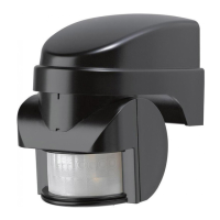
PIR Movement
Detector/Transmitter
For easy installation
and earlier detection
1. SPECTRA WIREFREE PIR MOVEMENT DETECTOR
This PIR Movement Detector with radio transmitter is only for use with the Spectra Wirefree
PIR Movement Detector and Receiver System. Use of an additional movement detector will
allow approach from other directions to activate lighting connected to a Receiver Unit. The
system code in this additional Detector must be set to the same system code as in the
Receiver Unit.
There is no limit to the number of PIR Movement Detectors which can be used with one
Receiver Unit.
2. PACK CONTENTS
1 wirefree (battery powered) 140° coverage PIR Movement Detector with built-in radio
transmitter. (Requires 1 x PP3/6LR61 9V Alkaline Battery)
2 Slot-in PIR lens screening panels
2 Plastic wall plugs plus 2 securing screws
3. TOOLS YOU WILL NEED
Flat bladed screwdriver, cross-head screwdriver, electric hand drill, drill bit to suit wall plug
dimensions.
4. SYSTEM CODING
The wirefree PIR detector communicates with its Receiver by means of a system code. This
is to prevent activation by other systems - such as a neighbour’s wirefree system, or your
own additional but separate system.
THE SYSTEM CODE in the Detector must match that in the Receiver Unit (see figs 2 and
3). See fig 11 on page 5 for instructions on how to open the Dectector unit. Make a note of
the Receiver Unit settings and, if necessary, simply move the slider-switches in the PIR
Detector unit to match.
IMPOR-
TANT:Mains electricity supply to the
5. PIR MOVEMENT DETECTOR FITTING INSTRUCTIONS
5.1. Where to position the PIR Movement Detector
■
Position the wirefree PIR Detector anywhere within 50 metres of the Receiver Unit, but avoid
mounting it on or near a large metal object, on something which is likely to move - such as a
small tree or loose fence panel - or where the light can shine directly at the PIR Detector. Also
avoid siting where the unit may detect any of the following: heat sources (extractor fans, tum-
ble dryer exhausts, etc.), reflective surfaces (pools of water, white-painted walls, etc.), nearby
overhanging branches (see fig 4).
■
The ideal height to mount your PIR Detector is 2.5 metres, which makes the best use of the
unit’s detection zones as shown in the diagrams (see figs 5 and 6). Mounting the PIR
Detector in a higher position (maximum 4 metres) may give a greater range, but the detec-
tion pattern will be less effective. The PIR Detector is much more sensitive to movement
across its field of vision (see fig 7A) than movement directly towards it, so site the unit so
that it looks across the normal approach to your property.
■ The Wirefree PIR Movement Detector has a swivel sensor head to allow you to adjust
the area of detection (see Testing Procedure in Section 6): tilting the head upwards will
increase the detection distance, tilting it downward will reduce the detection distance.
The sensor head will also turn to the left and right (see figs 8 and 9).
■ You can further tailor the detection area to suit your needs by using the slot-in lens
screening panels provided (see fig 10). To discover how much screening is needed, first
obscure the PIR unit’s lens with masking tape, progressively covering more of the lens until
the required detection area is achieved. Then simply cut a piece of the plastic screening
to cover the same area as the tape, remove the tape - being sure to remove any adhe-
sive residue left behind - and slot the screening into the PIR Detector (see fig 10).
N.B. If in normal conditions you find that something such as a tree or shrub is repeatedly acti-
vating the system, you can partially ‘mask’ the detector lens with electrical tape to stop the
detector ‘seeing’ the disturbance. As a guide, the top half of the PIR detector lens deals with
long-range detection, the bottom half is for short range. Alternatively, the PIR detector can
be easily re-positioned in a more suitable location.
5.2. Fitting the Wirefree PIR Movement Detector
NOTE: Before fixing the PIR unit to the mounting surface, it is advisable to check that the
system works correctly (i.e. that the transmitter and receiver are within radio range of each
other) by temporarily fixing the PIR Detector in the chosen location.
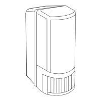
■ Open the PIR Detector by inserting a small slotted screwdriver into the slot at the base
of the unit. Push screwdriver gently to release catch and to allow front cover to be
opened fully - the cover is hinged at the top (see fig 11).
■ Check inside to identify the battery connector and the row of eight slider-switches (see fig 12).
■ Make sure you have set the same code in the PIR Detector as in the Receiver Unit (section 4).
■ Place the backplate of the unit in the desired position and mark the locations of the fix-
ing holes (fig 13). Next drill the holes to the required depth and insert the wall plugs.
■ Clip a 9V PP3 (6LR61) ALKALINE battery to the connector and place the battery in its
holder (see fig 14).
■ Fit the unit in place, close the cover and click it shut.
6. TESTING YOUR SYSTEM
Once your wirefree Detector is installed, test it by following the ‘Walk Test’ steps below.
1.
Set the two adjustment controls on the underside of the PIR Detector as follows:
TIME - turn fully anticlockwise to min. (see fig 15)
LUX - turn fully clockwise to max.
(see fig 16)
With these settings the system is in test mode and will work in full daylight. A small red light
(LED) behind the PIR Detector lens will illuminate briefly each time movement in front of the
PIR is detected.
6500