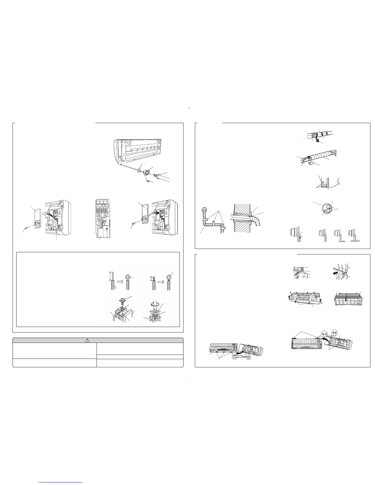
FINISHING
(1) Insulate between pipes.
● For rear, right, and bottom piping, overlap the connection pipe
heat insulation and indoor unit pipe heat insulation and bind
them with vinyl tape so that there is no gap.
● For left and left rear piping, butt the connection pipe heat insula-
tion and indoor unit pipe heat insulation together and bind them
with and vinyl tape so that there is no gap.
● For left and left rear piping, wrap the area which accommodates
the rear piping housing section with cloth tape.
● For left and left rear piping, bind the connection cord to the top
of the pipe with vinyl tape.
● For left and left rear piping, bundle the piping and drain hose
together by wrapping them with cloth tape over the range within
which they fit into the rear piping housing section.
(2) Temporarily fasten the connection cord along the connection pipe
with vinyl tape. (Wrap to about 1/3 the width of the tape from the
bottom of the pipe so that water does not enter.)
(3) Fasten the connection pipe to the outside wall with a saddle, etc.
(4) Fill the gap between the outside wall pipe hole and the pipe with
sealer so that rain water and wind cannot blow in.
(5) Fasten the drain hose to the outside wall, etc.
Fig. 16
Pipe
(Saddle)
(Outside wall cap)
(Sealer putty)
(Outdoors)
Fig. 15
Connection pipe
(heat insulation)
Bind the pipes together
to that there is no gap.
Overlap the insulation
Indoor unit pipe
(heat insulation)
Vinyl tape
Pipe
Drain hose
Cloth tape
Wrap with cloth tape
Wall
Check the following:
View from indoors
(1) Match the terminal block numbers and connection
cord colors with those of the outdoor unit.
Erroneous wiring may cause burning of the elec-
tric parts.
(2) Connect the connection cords firmly to the terminal
block. Imperfect installation may cause a fire.
CAUTION
(3) Always fasten the outside covering of the connection
cord with the cord clamp. (If the insulator is chafed,
electric leakage may occur.)
(4) Securely earth the power cord plug.
(5) Do not use the earth screw for an external connector.
Only use for interconnection between two units.
ELECTRICAL WIRING (INDOOR UNIT)
HOW TO THE INSTALL THE INTER-UNIT WIRE HARNESS
1. Remove the screws, then remove the conduit holder.
2. Fasten the inter-unit wire harness to the conduit holder using the lock nut.
IMPORTANT: Refer to fig. 20 about the length of inter-unit wire harness.
3. Use the screws to install the conduit holder with which Inter-unit wire har-
ness is included.
4. Remove the screws, then remove the wire clamper.
5. Connect inter-unit wire harness to the terminal.
Refer to the wiring diagram.
6. Use the screws to install the wire clamper.
ELECTRICAL WIRING (INDOOR UNIT)
1. Remove the screws, then remove the cord clamp.
2. Connect connection cord to the terminal.
Refer to the wiring diagram
3. Use the screws to install the cord clamp.
Connection cord
Screw
Cord clamp
(There is a
terminal block
inside.)
Connection cord
Screw
Cord clamp
A. For solid core wiring (or F-cable)
(1) Cut the wire end with a wire cutter or wire-cutting pliers, then strip
the insulation to about 15/16" (25 mm) to expose the solid wire.
(2) Using a screwdriver, remove the terminal screw(s) on the terminal
board.
(3) Using pliers, bend the solid wire to form a loop suitable for the termi-
nal screw.
(4) Shape the loop wire properly, place it on the terminal board and
tighten securely with the terminal screw using a screwdriver.
B. For strand wiring
(1) Cut the wire end with a wire cutter or wire-cutting pliers, then strip
the insulation to about 3/8" (10 mm) to expose the strand wiring.
(2) Using a screwdriver, remove the terminal screw(s) on the terminal
board.
(3) Using a round terminal fastener or pliers, securely clamp a round
terminal to each stripped wire end.
(4) Position the round terminal wire, and replace and tighten the termi-
nal screw using a screwdriver.
A. Solid wire
Strip 15/16" (25 mm)
Insulation
Loop
B. Strand wire
Strip 3/8" (10 mm)
Round
terminal
Wire
Screw with
special washer
Round
terminal
Terminal
board
Terminal block
Wire
Screw with
special washer
Round
terminal
HOW TO CONNECT WIRING TO THE TERMINALS
Fig. 14
Fig. 13
Fig. 12
WASHER
CONDUIT PLATE
CONDUIT CONNECTOR
SCREW
Left piping
Connection cord
Pipe
Drain hose
GOOD
Lifted up
Saddle
Wave End in water
BAD
Drain hose
BAD BAD
For connection from the left rear
Connection cord
Drain hose
Wall pipe
Connection pipe
FRONT PANEL REMOVAL AND INSTALLATION
THE INTAKE GRILLE REMOVAL
(1) Open the intake grille.
(2) Pull down the knob.
(3) Lift the intake grille upward, until the axle at the top of the intake
grille is removed.
THE INTAKE GRILLE INSTALLATION
(1) The fixing axle of the intake grille is installed on the Panel.
(2) Lay down the intake grille.
THE FRONT PANEL REMOVAL
(1) Remove intake grille (Reference the intake grille removal.)
(2) Remove four screws.
(3) The thumb is hung on the lower part as shown in the figure, and it
pulls to the front, pushing [-] mark , and bottom hooks (two posi-
tion) is removed from wall hook bracket.
(4) The front panel bottom is pulled to the front, and bottom hooks is
removed indoor unit.
(5) The front panel is pulled to the front, raising the upper surface,
and a front panel is removed.
THE FRONT PANEL INSTALLATION
(1) Firstly, fit the lower part of the front panel, and insert top and bot-
tom hooks. (Three top sides, six bottom sides)
(2) Four screws is attached.
(3) The intake grille is attached.
Fig. 4
Top holes (two sides)
Top hole (center)
Top hook (center)
Front panel
Top hooks
(two sides)
Indoor unit
Wall hook bracket
Front panel
Push
[-] mark
Push
Front panel
Bearing
Mounting shaft
Intake grille
Intake grille
Knob
Front panel
Screws
(4 position)
Bottom hole
(six position)
Front panel
Indoor unit
Bottom hooks
(six position)