Indoor unit drain hose (bottom)
Pipe (top)
Bottom
piping
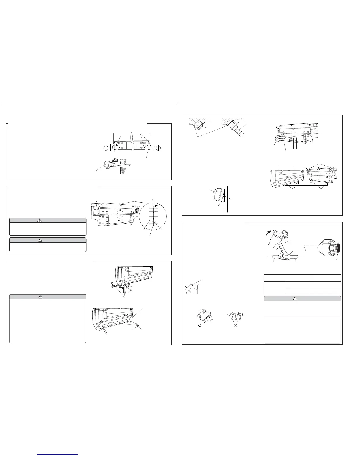
(1) Cut a 3-2/16’’(80 mm) diameter hole in the wall at the position shown
in (Fig.1).
(2) When cutting the wall hole at the inside of the installation
frame, cut the hole within the range of the left and right center
marks 3/8’’(10 mm) below the installation frame.
When cutting the wall hole at the outside of the installation frame,
cut the hole at least 3/8’’(10 mm) below less.
(3) Cut the hole so that the outside end is lower 3/16’’ to 3/8’’ (5 to 10 mm)
than the inside end.
(4) Always align the center of the wall hole. If misaligned, water leak-
age will occur.
(5) Cut the wall pipe to match the wall thickness, stick it into the wall
cap, fasten the cap with vinyl tape, and stick the pipe through the
hole. (The connection pipe is supplied in the installation set.)
(Fig.1)
(6) For left piping and right piping, cut the hole a little lower so that
drain water will flow freely. (Fig.1)
Fig. 1
Fasten with
vinyl tape
(Wall cap)
(Wall pipe)
(Inside)
Wall
(Outside)
Wall hook
bracket
Counter
weight
(1) Install the wall hook bracket so that it is correctly positioned hori-
zontally and vertically. If the wall hook bracket is titled, water will
drip to the floor.
(2) Install the wall hook bracket so that it is strong enough to with-
stand the weight of an adult.
● Fasten the wall hook bracket to the wall with 6 or more screws
through the holes near the outer edge of the bracket.
● Check that there is no rattle at the wall hook bracket.
WARNING
If the wall pipe is not used, the cord interconnecting
the indoor and outdoor units may touch metal and
cause electric leakage.
CAUTION
Install the wall hook bracket horizontally and perpen-
dicularly.
Fig. 2
Wall hook bracket
Tapping screw
Center notch
String
[Rear piping, Right piping, Bottom piping]
● Install the indoor unit piping in the direction of the wall hole and
bind the drain hose and pipe together with vinyl tape. (Fig. 3)
● Install the piping so that the drain hose is at the bottom.
● Wrap the pipes of the indoor unit that are visible from the outside
with decorative tape.
[For Left rear piping, Left piping]
Interchange the drain cap and the drain hose.
Fig. 3
Right piping
Bind with vinyl tape
For left outlet piping,
cut off the piping
outlet cutting groove
with a hacksaw.
Indoor unit
drain hose
Remove the drain cap
by pulling at the
projection at the end
of the cap with pliers, etc.
Drain cap
Lower
3-2/16’’(80 mm)
dia. hole
Center mark
3/8’’(10 mm)
or over
3/16’’ to 3/8’’
(5 to 10 mm)
low
3/8’’(10 mm)
or over
Lower
3-2/16’’(80 mm) dia. hole
(A 2-9/16’’(65mm)
diameter hole is
possible for the right-
hand side.)
Hook
Rear piping
4. CONNECTING THE PIPING
● For left piping and left rear piping, align the marks on the wall
hook bracket and shape the connection pipe.
● Bend the connection piping at a bend radius of 2- 3/4’’(70 mm) or
more and install no more than 1- 3/8’’(35 mm) from the wall.
● After passing the indoor piping and drain hose through the wall
hole, hang the indoor unit on the hooks at the top and bottom of
the wall hook bracket.
[Installing the indoor unit]
● Hang the indoor unit from the hooks at the top of the wall hook
bracket.
● Insert the spacer, etc. between the indoor unit and the wall hook
bracket and separate the bottom of the indoor unit from the wall.
CONNECTION
(1) Install the outdoor unit wall cap (supplied with the optional in-
stallation set or procured at the site) to the wall pipe.
(2) Connect the outdoor unit and indoor unit piping.
(3) After matching the center of the flare surface and tightening the
nut hand tight, tighten the nut to the specified tightening torque
with a torque wrench. (Tighten the flare nut of the outdoor unit
3-way valve after air purging.)
FLARING
(1) Cut the connection pipe to the necessary length with a pipe cutter.
(2) Hold the pipe downward so that cuttings will not enter the pipe
and remove the burrs.
(3) Insert the flare nut onto the pipe and flare the pipe with a flaring
tool.
Check if [L] is flared uniformly
and is not cracked or scratched.
L dimension
Thin pipe 1/4” (6.35 mm)dia. ...... 1/16” (1.4 to 1.7 mm)
Thick pipe 3/8” (9.52 mm)dia. ...... 5/64” (1.8 to 2.0 mm)
Fig. 5
Tighten with two wrenches.
Torque wrench
Wrench (fixed)
Flare nut
Indoor unit pipe
Connection pipe
To prevent gas leakage,
coat the flare surface
with refrigerator oil.
BENDING PIPES
The pipes are shaped by your hands. Be careful not to collapse them.
Do not bend the pipes in an angle more than 90°.
When pipes are repeatedly bent or stretched, the material will harden,
making it difficult to bend or stretch them any more. Do not bend or stretch
the pipes more than three times.
OK NO
Extend the pipe
by unwinding it.
2. INSTALLING THE WALL HOOK BRACKET
INDOOR UNIT
1. CUTTING THE HOLE IN THE WALL FOR THE CONNECTING PIPING
3. FORMING THE DRAIN HOSE AND PIPE
Indoor unit
Wall hook bracket
(Spacer)
CAUTION
(1) Fasten a flare nut with a torque wrench as in-
structed in this manual. If fastened too tight, the
flare nut may be broken after a long period of time
and cause a leakage of refrigerant.
(2) During installation, make sure that the refrigerant
pipe is attached firmly before you run the compres-
sor. Do not operate the compressor under the con-
dition of refrigerant piping not attached properly
with 2-way or 3-way valve open. This may cause
abnormal pressure in the refrigeration cycle that
leads to breakage and even injury.
Drain cap
Insert the drain cap and drain hose until it butts
against the drain port.
Indoor unit
drain hose
CAUTION
(1)
In order to align the drain hose and drain cap, be
sure to insert securely and vertically. Incline in-
sertion will cause water leakage.
(2)
When inserting, be sure not to attach any mate-
rial besides water. If any other material is at-
tached, it will cause deterioration and water leak-
age.
(3)
After removing drain hose, be sure not to forget
mounting drain cap.
(4) Be sure to fix the drain hose with tape to the bot-
tom of piping.
Fig. 4
Connection pipe
(1/4” (6.35 mm) dia.)
Connection pipe
(3/8’’(9.52 mm) dia.)
Align the marks.
Bend 2-3/4’’(R70)
with a pipe bender
After hooking the indoor unit to the top hook, hook the fittings of the
indoor unit to the two bottom hooks while lowering the unit and
pushing it against the wall.
Top hooks
Indoor unit
(Fitting)
Bottom hooks
Wall hook
bracket
Flare nut
1/4” (6.35 mm)dia.
3/8” (9.52 mm)dia.
Tightening torque
11.57 to 13.02 ft•lbs
(160 to 180 kgf•cm)
21.70 to 30.38 ft•lbs
(300 to 420 kgf•cm)
Table 2 Flare nut tightening torque
Tightening torque standard
(using a 20 cm wrench)
Wrist strength
Arm strength
 Loading...