Do you have a question about the Friedrich MR18Y3H and is the answer not in the manual?
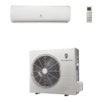
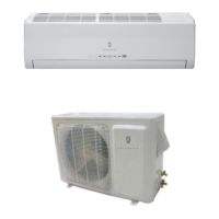
Lists available indoor unit models for the product line.
Lists available outdoor unit models for the product line.
Lists authorized distributors for replacement parts.
Provides contact details for technical assistance and support services.
Details electrical characteristics like voltage, current, and power consumption.
Lists fan motor speeds and power sources for indoor and outdoor units.
Provides decibel ratings for indoor and outdoor unit noise during operation.
Information on compressor type, refrigerant charge, and pipe length limits.
Physical measurements and weight specifications for indoor and outdoor units.
Illustrates the direction of refrigerant flow for cooling and heating modes.
Specifies the required diameters for liquid and gas refrigerant lines.
Electrical schematic for the MW18Y3H/MR18Y3H indoor unit.
Electrical schematic for the MW18Y3H/MR18Y3H outdoor unit.
Electrical schematic for the MW24Y3H/MR24Y3H indoor unit.
Electrical schematic for the MW24Y3H/MR24Y3H outdoor unit.
Identifies the control unit models for indoor PCBs.
Shows connections for the wired remote control unit.
Wiring details for louver and fan motors on the indoor unit.
Connections for pipe thermistor, room thermistor, and indicator PCB.
Diagram showing components and connections for the indicator PCB assembly.
Diagram of EMI filter and power supply connections for the outdoor unit.
Shows connections for inverter and transistor PCB assemblies.
Diagrams for 4-way valve, expansion valve, thermistors, and compressor.
Lists PCB cases, inverter case, and ACTPM components.
Details thermistors, choke coil, and terminal components.
Shows connections for thermistors and heat exchanger.
Diagram of the IPM PCB assembly with components and wiring.
Diagram of the capacitor PCB assembly with components and wiring.
Diagram of the power supply PCB for MR18Y3H with components and wiring.
Diagram of the power supply PCB for MR24Y3H with components and wiring.
Diagram of the capacitor PCB for MR24Y3H with components and wiring.
Detects serial communication errors between units.
Indicates issues with indoor unit temperature sensors.
Indicates issues with outdoor unit temperature sensors.
Flags faults in the indoor unit's control system.
Flags faults in the outdoor unit's control system.
Detects abnormalities in the indoor fan motor operation.
Indicates problems with the refrigerant flow or pressure.
Signals issues with optional functions or features.
Indicates errors related to model identification or configuration.
Lists parts for the front panel, intake grille, and clamping grille.
Lists air filter and remote control parts.
Lists drain cap, drain hose, and bush parts.
Lists pillar, joint, and fan guard related parts.
Lists evaporator, water seal, and bracket parts.
Lists filter guide, filter guard, and fan assembly parts.
Details DC brushless motor and various step motor parts.
Lists indicator PCB assembly and pipe thermistor parts.
Lists top panel, valve cover, and protective net parts.
Details motor bracket and propeller fan assembly parts.
Lists valve plate and condenser assembly parts.
Details compressor sub assembly, solenoid, and pressure switch.
Lists expansion valve, coil, and muffler parts.
Details power supply PCBs and transistor PCB assemblies.
Lists capacitor PCBs, choke coil, and terminal parts.
Lists discharge, outdoor, compressor, and heat exchanger thermistors.
| Brand | Friedrich |
|---|---|
| Model | MR18Y3H |
| Category | Air Conditioner |
| Language | English |