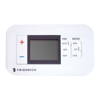
Icon Descriptions
Specifications
Electrical rating: •24VAC(18-30VAC)
•1ampmaximumperterminal
•3ampmaximumtotalload
Temperature control range: 45°Fto90°F(7°Cto32°C)Accuracy:±1°F(±0.5°C)
System congurations:2-stageheat,1-stagecool,heatpump,electric
Timing:Anti-shortCycle:4minutes(bypassanti-shortcycledelaybyreturningtoOFFmodefor5seconds)
BacklightOperation:10seconds
Terminations:R,C,GL,GH,O/B,Y,W
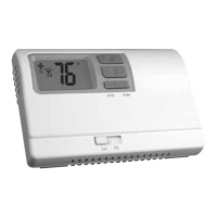
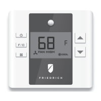
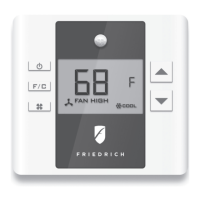
RT6
Electronic Thermostat
Installation, Operation & Application Guide
• 1-Stage Heat/1-Stage Cool Systems
• Congurable to: 2-stage heat pump
• Large Display With Backlight
• Selectable Fahrenheit or Celsius
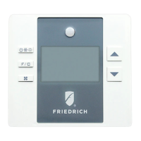
Parts Diagram
Conguration
switch
Lo/Hifan
switch
Reset
switch
Left(system)
button
Right(fan)
button
Downbutton
Upbutton
YO/BGHGLCR W
RESET CONFIG
Package Contents/Tools Required
Package includes:RT6thermostatonbase,thermostatcover,wiringlabels,screwsandwallanchors,Installation,
OperationandApplicationGuide
Tools required for installation:Drillwith3/16”bit,hammer,screwdriver
Important Safety Information
WARNING!
:
Always turn off power at the main power supply before installing, cleaning, or removing
thermostat.
• Thisthermostatisfor24VACapplicationsonly;donotuseonvoltagesover30VAC
• Allwiringmustconformtolocalandnationalelectricalandbuildingcodes
• Donotuseairconditioningwhentheoutdoortemperatureisbelow50degrees;thiscandamageyourA/Csystem
andcausepersonalinjuries
• Usethisthermostatonlyasdescribedinthismanual
To Remove Existing Thermostat
ELECTRICAL SHOCK HAZARD
– Turn off power at the main service panel by removing the fuse
or switching the appropriate circuit breaker to the OFF position before removing the existing
thermostat.
1. Turnoffpowertotheheatingandcoolingsystembyremovingthefuseorswitchingtheappropriatecircuit
breakeroff.
2. Removecoverofoldthermostat.Thisshouldexposethewires.
3. Labeltheexistingwireswiththeenclosedwirelabelsbeforeremovingwires.
4. Afterlabelingwires,removewiresfromwireterminals.
5. Removeexistingthermostatbasefromwall.
6. Refertothefollowingsectionforinstructionsonhowtoinstallthisthermostat.
To Install Thermostat
ELECTRICAL SHOCK HAZARD
– Turn off power at the main service panel by removing the fuse
or switching the appropriate circuit breaker to the OFF position before removing the existing
thermostat.
IMPORTANT:Thermostat installation must conform to local and national building and electrical codes and
ordinances.
Note:Mount the thermostat about ve feet above the oor. Do not mount the thermostat on an outside wall, in
direct sunlight, behind a door, or in an area affected by a vent or duct.
1. Turnoffpowertotheheatingandcoolingsystembyremovingthefuseorswitchingtheappropriatecircuit
breakeroff.
2. Toremovecover,pullgentlyattheseamatthetop.
3. Putthermostatbaseagainstthewallwhereyouplantomountit(Besurewireswillfeedthroughthewire
openinginthebaseofthethermostat).
4. Marktheplacementofthemountingholes.
5. Setthermostatbaseandcoverawayfromworkingarea.
6. Usinga3/16”drillbit,drillholesintheplacesyouhavemarkedformounting.
7. Useahammertotapsuppliedanchorsinmountingholes.
8. Alignthermostatbasewithmountingholesandfeedthecontrolwiresthroughslitinthermalintrusionbarrierand
intowireopening.
9. Usesuppliedscrewstomountthermostatbasetowall.
10. Insertstripped,labeledwiresinmatchingwireterminals.
CAUTION!:Be sure exposed portion of wires does not touch other wires.
11. Gentlytugwiretobesureofproperconnection.Doublecheckthateachwireisconnectedtotheproper
terminal.
12. Turnonpowertothesystematthemainservicepanel.
13. Congurethermostattomatchthetypeofsystemyouhave.
14. Replacecoveronthermostatbysnappingitinplace.
15. Testthermostatoperationasdescribedin“TestingtheThermostat”.
Terminal Designator Descriptions
R – 24VAChot
C – 24VACcommon
O/B – Congurable
O–Coolactivereversingvalve(FreidrichPTHP)
B–Heatactivereversingvalve(FreidrichVert-I-Pak,Kuhl+HP)
Y – 1ststagecool,1ststageheatforheatpumps
W – 1ststageheatfornon-heatpumpsystems,auxiliaryheatforHPsystems
GL – Lowfan
GH – Highfan
RT6 Output Chart
Wiring Diagrams
Heat/Cool Systems Heat pump with electric backup
120
VAC
24VAC
LowFan
HighFan
Compressor
ReversingValve
AuxiliaryHeat
Transformer
C
GL
GH
O/B
Y
W
R
120
VAC
24VAC
LowFan
HighFan
Cool
Heat
Transformer
C
GL
GH
O/B
Y
W
R
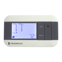
Fanoperationicon
Coolingoperationicon
Heatingoperationicon
Heatsetpointwhenblinking
Coolsetpointwhenblinking
Roomtemperature
offsetactivated
COOL
HEAT
Configuration
1
ST
Cool 1
ST
Heat 2
ND
Heat
Heat/CoolandsinglestageHPmodels ELC Y,G W,G,B N/A
PDH(PTHP)modelsonly HP‘O’Cong Y,G,O Y,G Y,W,G
TheRT6thermostatiscongurablefordifferentsystems.Thecongurationdirectlyaffectstheoutputs.
Usetheoutputcharttocorrectlycongureandwirethethermostattoyoursystem.
OFF
1. VerifytheRT6isintheOFFmode.
PresstheSYS(left)buttonuntiloffmodedisplays.
2. Removethecoverofthethermostatbygentlypullingnearoneofthecornersat
thetopofthethermostat.
Configuration Mode
Presstheupordownbuttontochangesettingswithineachscreen.
Toexitcongurationmode,presstheCONFIGswitchfor1second.
Presstherightbuttontoadvancetothenextscreen.
Note:Pressing the
left
button will return you to the previous screen.
Down
button
Up
button
Left
button
Right
button
ThecongurationmodeisusedtosettheRT6tomatchyourheating/coolingsystem.TheRT6functionswithheat
pump,airconditioning,orelectricheatsystems.
Note:
Thermostat comes congured for 1-stage heat / 1-stage cooling for use with all heat/cool and single-stage heat
pump models.For Friedrich PTHP models follow the instructions below to congure the thermostat for two-stage
heat pump operation using the ‘O’ terminal.
ToconguretheRT6,performthefollowingsteps:
3. PresstheCONFIGbuttonfor1secondwhiletheRT6isinOFF mode.
CONFIG