4
920-075-09
General Specications
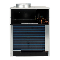
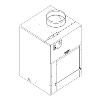
Vert-I-Pak
®
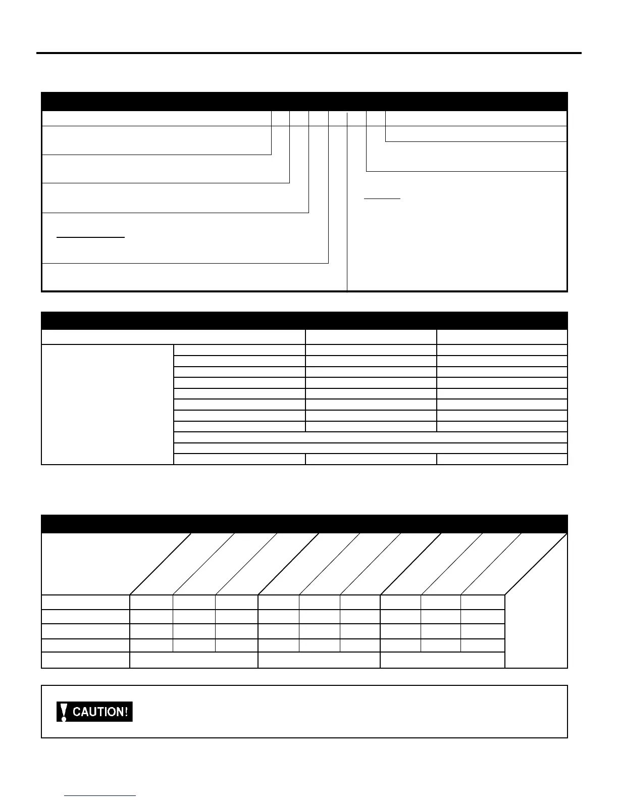
Model Identication Guide
Electrical Data
MODEL: V(E,H)A09 V(E,H)A12 V(E,H)A18
Voltage (V) 230 / 208 230 / 208 230 / 208
Refrigerant R-22 R-22 R-22
Chassis Width 23.125" 23.125" 23.125"
Chassis Depth 23.125" 23.125" 23.125"
Chassis Height ** 32.25" 32.25" 32.25"
Shipping W x D x H 26.00" x 28.50" x 35.00" 26.00" x 28.50" x 35.00" 26.00" x 28.50" x 35.00"
Supply Duct Collar *** 10" 10" 10"
Drain Connection 3/4" FPT 3/4" FPT 3/4" FPT
Min. Circuit Amps See Chassis Nameplate
CFM Indoor See Charts 2 & 3 (Page 10)
Max. Duct ESP .3 in. water .3 in. water .3 in. water
NOTES:
** Height includes 2" duct collar & isolators under unit.
*** Factory collar accepts 10" ex duct.
ELECTRIC HEATER SIZE
A Series
25 = 2.5 KW
34 = 3.4 KW
50 = 5.0 KW*
75 = 7.5 KW**
MODEL NUMBER V E A 09 K 34 RT H
ENGINEERING CODE
OPTIONS
RT = Standard Remote Operation
* Not available on 9000 BTU models.
** 24000 BTU only.
VOLTAGE
K = 208/230V-1Ph-60Hz
NOMINAL CAPACITY
A Series (Btu/h)
09 = 9,000
12 = 12,000
DESIGN SERIES
A = 32"/47" Cabinet
SERIES
V=Vertical Series
18 = 18,000
24 = 24,000
E =Cooling with electric heat
H =Heat Pump
Refer to electrical data chart for heater/unit compatibility.
Voltage ( V) 230/208 230/208 230/208 230/208 230/208 230/208 230/208 230/208 230/208
LRA - Comp. (A) 21 21 21 24.0 24.0 24.0 47 47 47
Cooling Current (A) 4.4/4. 9 4.4/4. 9 4.4/4.9 5.5/6.1 5.5/6.1 5.5/6.1 9.2/10.2 9.2/10.2 9.2/10.2
MIN. Ckt. Amps (A) 15 20 30 15 20 30 15 20 30
Power Connection HARD WIRED HARD WIRED HARD WIRED
V(E,H)A09K25
V(E,H)A09K34
V(E,H)09K50
V(E,H)A12K25
V(E,H)A12K34
V(E,H,)A12K50
V(E,H)A18K25
V(E,H)A18K50
V(E,H)A18K34
Model
Chassis Specications
Important: all 208/230v chassis must be hard wired with properly sized breaker. See nameplate for specic chassis
electrical requirements. See page 8 - Figure 5 for unit wiring and wall thermostat wiring. See page 8 for wire size. Use
HACR type breakers to avoid nuisance trips. All eld wiring must be done in accordance with nec and local codes.