EasyManua.ls Logo

Friedrich VERT-I-PAK R410A User Manual

Friedrich VERT-I-PAK R410A
61 pages
To Next Page IconTo Next Page
Page #1 background imageLoading...
Page #1 background image
V(E, H)A09K25L-* V(E, H)A09K34L-* V(E, H)A09K50L-*
V(E, H)A12K25L-* V(E, H)A12K34L-* V(E, H)A12K50L-*
V(E, H)A18K25L-* V(E, H)A18K34L-* V(E, H)A18K50L-*
V(E, H)A24K25L-* V(E, H)A24K34L-* V(E, H)A24K50L-*
V(E, H)A24K75L-* V(E, H)A24K10L-*
VPK-ServMan-L (4-11)
2011-2012 Service/Parts Manual
L-B Suffi x, R410A Models
A Series (Electronic Controls)
Single Package Vertical Air Conditioning System
9-18K 24K
*Last Character May Vary

Table of Contents

Question and Answer IconNeed help?

Do you have a question about the Friedrich VERT-I-PAK R410A and is the answer not in the manual?

Friedrich VERT-I-PAK R410A Specifications

General IconGeneral
BrandFriedrich
ModelVERT-I-PAK R410A
CategoryAir Conditioner
LanguageEnglish

Summary

IMPORTANT SAFETY INFORMATION

Personal Injury and Death Hazards

Covers electrical, refrigeration, and mechanical hazards with warnings and precautions.

INTRODUCTION

IMPORTANT SAFETY INFORMATION

Property Damage Hazards

Covers fire and water damage warnings and precautions.

Model Identification Guide

VPAK Serial Number Identification Guide

Explains how to interpret the unit's serial number for manufacturing details.

ELECTRICAL REQUIREMENTS

Chassis Specifications

TECHNICAL SERVICE DATA

Cooling Performance Data

Provides performance metrics for various cooling conditions.

ELECTRONIC CONTROL SEQUENCE OF OPERATION

Compressor and Reversing Valve Control

Describes operation logic for compressor and reversing valve.

Low Voltage Interface Connections

Connecting a Remote Wall Thermostat

Guides on wiring a remote wall thermostat to the unit's control board.

COMPONENTS IDENTIFICATION

Error Codes and Alarm Status

Unit Control Panel

Describes the display, error codes, and maintenance indicator.

COMPONENTS TESTING

Testing the Diagnostic Service Module

Procedure to test the diagnostic service module's functionality.

Testing the Electronic Control Board

Steps to test voltage and continuity on the control board.

Blower/Fan Motor Testing

Capacitor Testing

Guidelines for checking capacitor serviceability and connections.

Heater Elements and Limit Switches

Testing Heating Elements and Limit Switches

Procedures for testing heating elements and limit switches.

External Static Pressure

Checking External Static Pressure

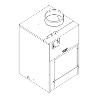
Explains measuring external static pressure for airflow determination.

REFRIGERATION SEQUENCE OF OPERATION

SEALED REFRIGERATION SYSTEM REPAIRS

Refrigerant Charging

Emphasizes the importance of proper refrigerant charge for unit performance.

Method Of Charging / Repairs

Undercharged Refrigerant Systems

Describes symptoms and checks for systems with insufficient refrigerant.

Overcharged Refrigerant Systems

Restricted Refrigerant System

HERMETIC COMPONENTS CHECK

Metering Device Check

Details checking capillary tube systems for restrictions.

REVERSING VALVE DESCRIPTION/OPERATION

Testing the Coil

Checks solenoid coil continuity.

Checking the Reversing Valve

Verifies valve shift function between modes.

COMPRESSOR CHECKS

Locked Rotor Voltage (L.R.V.) Test

Tests compressor voltage under a stalled condition.

Checking the Overload

Diagnoses issues related to the compressor's overload protector.

Single Phase Resistance Test

External and Internal Overload Testing

Procedures for testing external and internal overloads.

COMPRESSOR REPLACEMENT

ROUTINE MAINTENANCE

ELECTRICAL TROUBLESHOOTING CHARTS

Cooling Troubleshooting

Guides for diagnosing cooling operation issues.

ELECTRICAL TROUBLESHOOTING CHART - COOLING 24K BTU

ELECTRICAL TROUBLESHOOTING CHART HEAT PUMP

Heat Pump Mode

Troubleshooting steps specific to heat pump operational issues.

REFRIGERANT SYSTEM DIAGNOSIS CHARTS

Cooling Diagnosis

Charts for diagnosing cooling problems based on refrigerant pressures.

Heating Diagnosis

Charts for diagnosing heating problems based on refrigerant pressures.

WIRING DIAGRAMS

Remote Wall Thermostat Wiring

Diagrams showing thermostat connection configurations.

Electrical and Thermostat Wiring - Cool Models

Specific wiring diagrams for cool units.

Electrical and Thermostat Wiring - Heat Pump Models

Specific wiring diagrams for heat pump units.

Accessories

LIMITED WARRANTY

TECHNICAL SUPPORT CONTACT INFORMATION

Related product manuals