Be careful with the sharp edges and corners.
Wear protective clothing and gloves, etc.
installation.
applied.
death.
Servicing / Chassis Quick Changeouts
.
Warranty
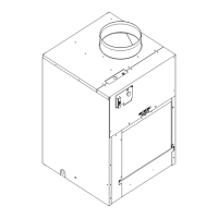
To Remove the Chassis from the Closet:
B. Switch the wall Thermostat off.
C. Pull the Power Disconnect located in the front of the chassis.
A. Disconnect the power coming into the unit from the main
breaker panel or the closet mounted disconnect.
D. Disconnect the electrical connection.
E. Disconnect the duct work.
G. Slide the chassis out of the wall plenum.
F. Disconnect condensate drain on 9-18,000 BTU models.
H. Lift the chassis out of the utility closet.
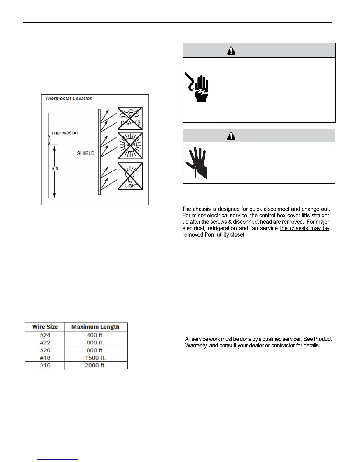
Remote Wall Thermostat Location
The thermostat should not be mounted where it may be affected by drafts,
discharge air from registers (hot or cold), or heat radiated from the sun
appliances, windows etc.. The thermostat should be located about 5 Ft.
above the floor in an area of average temperature, with good air circulation.
Mercury bulb type thermostats MUST be level to control temperature
accurately to the desired set-point. Electronic digital type thermostats
should be level for aesthetics.
Note: An improperly operating or poorly located remote wall thermostat
can be the source of perceived equipment problems. A careful check of the
thermostat’s location and wiring must be made then to ensure that it is not
the source of problems.
Desk Control
The unit’s electronic control has built-in provisions for connection to an
external switch to control power to the unit. The switch can be a central
desk control system or even a normally open door switch.
For desk control operation, connect one side of the switch to the D1
terminal and the
other to the D2 terminal (See page 12). Whenever the
switch closes, the unit operation will stop.
Maximum Wire Length for Desk Control Switch
Auxiliary Fan Control
The electronic control also has the ability to control a 24 VAC relay to
activate an auxiliary, or transfer fan. The outputs are listed as F1 and F2 on
the interface connector (See page 12).
To connect the relay, simply wire one side of the relay to F1 and the other
side to F2. Anytime that the fan runs, the terminals will send a 24 VAC
sign
al to the relay. The relay must be 24 VAC, 50mA or less.
Note: The Desk Control, Auxiliary Fan relay and wires must be field supplied.
 Loading...