Do you have a question about the Friedrich Wallmaster WET10A33A and is the answer not in the manual?
Details crucial safety precautions and potential hazards for installation and service.
Outlines risks of injury or death associated with improper operation and maintenance.
Highlights dangers and necessary precautions related to electrical components and connections.
Details safety measures for working with refrigeration systems and refrigerants.
Addresses risks associated with moving parts, sharp edges, and fins.
Lists categories of hazards that can cause property damage.
Lists precautions to prevent fire hazards during operation and maintenance.
Provides warnings and guidelines to prevent water damage to the unit and property.
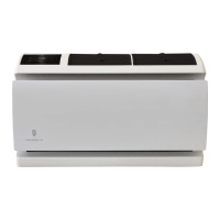
Describes the new features for controlling and programming the Wallmaster unit.
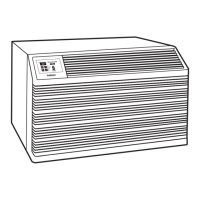
Illustrates where to find the model and serial number on the unit.
Provides a breakdown of how to interpret the unit's model number.
Explains the components and meaning of the unit's serial number.
Presents performance data for the refrigeration systems of various models.
Provides electrical specifications including voltage, amperage, and breaker ratings.
Discusses heating performance characteristics and conditions.
Explains the operation and conditions for the defrost control system.
Explains the operation and conditions for the defrost drain system.
Details the required clearances for proper installation to ensure optimal performance.
Specifies circuit requirements, breaker types, power cords, and receptacle compatibility.
Guides on how to adjust the direction and path of the airflow from the unit.
Describes the functions and layout of the unit's control panel and display.
Details the buttons, icons, and display elements of the control panel.
Explains how to navigate through the unit's sub-menu options.
Describes how to move forward and backward within the sub-menu structure.
Details how to set the upper and lower setpoint limits for the unit's operation.
Explains the procedure for setting the unit's timer functions.
Describes how to toggle the temperature display between Fahrenheit and Celsius.
Guides on how to activate and set a four-digit passcode to lock the control panel.
Explains how to access and view diagnostic codes for troubleshooting.
Details how to enable and connect the unit to a Wi-Fi network.
Provides step-by-step instructions for connecting the unit to a Wi-Fi network.
Offers solutions for common issues encountered during Wi-Fi setup and connection.
Describes the functions of system modes, fan settings, and other controls on the unit.
Details how to install batteries and operate the remote control for the unit.
Provides general information about the unit's cooling capabilities and normal operation.
Highlights specific operational differences for heat pump models during heating.
Explains the control logic for the compressor and reversing valve in different modes.
Describes the operational cycle and logic for the unit when in cooling mode.
Explains the operational control for units providing heat, including heat pump and electric heat.
Details the complex heating control for units with both heat pump and electric heat.
Explains the unit's behavior during system failures affecting heat pump operation.
Describes the operation of units that use electric heat exclusively.
Explains the automatic changeover between cooling and heating modes.
Details the delay mechanism preventing rapid mode switching.
Explains the feature that de-energizes the compressor for a set period.
Describes the delay applied to the fan during cooling cycles.
Explains the delay applied to the fan during heating cycles.
Details the delay in relay activation for fan speed changes.
Describes the operation when the unit is set to fan only mode.
Outlines the fan modes available on the front panel.
Explains how the fan speed icon is displayed based on selection.
Explains the fundamental principles and cycle of the refrigeration system.
Provides instructions for safely removing and reinstalling the front cover and air filter.
Guides on inspecting and cleaning the unit's coils, chassis, and base pan.
Instructions for cleaning the decorative front panel and cabinet.
Notes on the lubrication and maintenance of the fan motor and compressor.
Details on inspecting and cleaning the wall sleeve and drain system.
Guidance on inspecting and cleaning blower and fan components.
Describes periodic inspection of electrical and electronic components.
Recommends cleaning the air filter monthly for optimal operation.
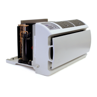
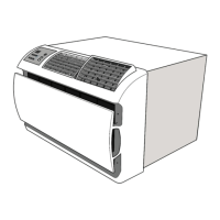
Step-by-step instructions for removing and reinstalling the unit's chassis.
Explains the importance and process of proper refrigerant charging for unit operation.
Describes symptoms and checks for systems with insufficient refrigerant charge.
Details symptoms and causes of overcharged refrigerant systems.
Covers troubleshooting for partial and complete restrictions in the refrigerant system.
Outlines the Weighed in Charge Method for charging sealed systems.
Details checks for hermetic components, including compressors and motors.
Explains how to check capillary tube metering devices for restrictions.
Describes the function and operation of the check valve in heat pump models.
Explains the function and operation of the 4-way reversing valve.
Guides on testing the electrical continuity and grounding of the reversing valve solenoid coil.
Describes a method to check reversing valve slide position using temperature.
Provides steps to check the reversing valve operation by switching between heating and cooling modes.
Step-by-step instructions for replacing the reversing valve, including brazing precautions.
A diagnostic chart correlating valve symptoms with possible causes and corrections.
Covers various checks for compressor functionality, including voltage, amperage, and overloads.
Explains how to perform a Locked Rotor Voltage test on the compressor.
Details how to measure the compressor's running amperage and locked rotor amperage.
Describes how to test external and internal compressor overloads.
Guides on testing compressor winding resistance using an ohmmeter.
Explains how to check for a grounded compressor body.
Describes how to diagnose compressor inefficiency due to valve issues.
Step-by-step instructions for replacing a compressor, including safety precautions.
Provides specific steps for compressor replacement following a burnout.
Offers troubleshooting and service tips specific to rotary and scroll compressors.
Describes the fan motor and its self-resetting overload protection.
Guides on testing the fan motor's operation and speed settings.
Explains the function of capacitors and safety precautions when handling them.
Details how to test capacitors using a capacitor analyzer.
Provides guidance on proper connection of capacitor terminals to avoid damage.
Describes the heating element, its safety features, and testing procedures.
Explains the heating element's operation specific to heat pump models.
Details how to test the heating element's resistance.
Explains the function and operation of the temperature-sensitive drain pan valve.
Provides troubleshooting steps if the user interface or control board is not functioning.
Describes the location and function of the unit's four thermistors.
Guides on testing thermistors for proper resistance values.
Identifies the various components and connection points on the electronic control board.
Step-by-step instructions for removing and replacing the electronic control board.
Detailed guide for removing and replacing the user interface unit.
Provides a guide for determining the correct cooling capacity (BTU) based on room size.
Lists diagnostic codes generated by the control board and their corresponding problems and actions.
Offers solutions for common operational issues like unit not operating or tripping breakers.
Addresses specific troubleshooting for units that provide both cooling and heating.
Provides a diagnostic flow chart for refrigerant system issues during heating.
Offers a chart for troubleshooting electrical issues in heat pump systems.
Presents a flow chart for diagnosing refrigerant system problems during the cooling cycle.
Explains the purpose and structure of the illustrated parts catalog.
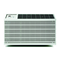
Describes available exterior grille options and their features.
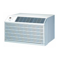
Information about the WSE wall sleeve and its included components.
Lists and describes accessories for unit installation, such as drain kits.
Outlines the warranty coverage for parts during the first year of ownership.
Details the warranty coverage for the sealed refrigerant system from the second to fifth year.
Specifies warranty applicability, exclusions, and limitations.
Provides instructions on how to obtain warranty service and contact information.
States limitations on implied warranties and manufacturer liability for damages.
Lists authorized distributors for Friedrich replacement parts.
Provides contact details for technical support and customer service.
| Brand | Friedrich |
|---|---|
| Model | Wallmaster WET10A33A |
| Category | Air Conditioner |
| Language | English |