Before Starting
Tools You Will Need
For leveling legs and Anti-Tip Bracket:
Adjustablewrench orchannel lockpliers
5/16" Nutdriver or Flat Head Screw Driver
• Electric Drill & 1/8" Diameter Drill Bit (5/32" Masonry Drill
Bit if installing in concrete)
For gas supply connection:
Pipe wrench _
For burner flame adjustment:
Phillipshead _ and
blade-typescrewdrivers
For gas conversion (LP/Propane or Natural):
• Open end wrench - 1/2"
Additional Materials You Will Need
• Gas line shut-off valve _,'_
Pipe joint sealant that resists action of LP/Propane gas
• A new flexible metal appliance conduit (1/2" NPT x 3/4"
or 1/2"I.D.) must be design certified by CSA International.
Because solid pipe restricts moving the range we
recommend using a new flexible conduit (4 to 5 foot
length) for each new installation and additional
reinstallations.
• Always use the (2) new flare union adapters (1/2" NPT x
3/4" or 1/2" I.D.) supplied with the new flexible appliance
conduit for connection of the range.
Normal Installation Steps
1. Anti-Tip Bracket Installation Instructions
Important Safety Warning
To reduce the risk of tipping of the range, the range must be
secured to the floor by properly installed anti-tip bracket and
screws packed with the range. Failure to install the anti-tip
bracket will allow the range to tip over if excessive weight is
placed on an open door or if a child climbs upon it. Serious
injury might result from spilled hot liquids or from the range
itself.
If range is ever moved to a different location, the anti-tip
brackets must also be moved and installed with the range.
Instructions are provided for installation in wood or cement
fastened to either the floor or wall. When installed tothe wall,
make surethat screws completely penetrate dry wall and are
secured in wood or metal. When fastening to thefloor or wall,
be sure that screws do not penetrate electrical wiring or
plumbing.
A.
S.
3
Locate the Bracket Using theTemplate- (Bracketmay
be locatedoneitherthe leftor rightsideofthe range. Use
theinformation below to locatethe bracket iftemplateis
not available). Mark thefloor or wall where left or right
side ofthe rangewillbelocated. Ifrear ofrange isagainst
thewallornofurther than 1-1/4"fromwallwheninstalled,
you may use the wall or floormount method. If molding
is installedand does not allow the bracket to fit flush
against thewall,remove moldingor mountbracket tothe
floor.For wall mount, locate the bracket by placingthe
backedge of thetemplate against the rear wall and the
side edge oftemplateonthe mark made referencingthe
side of the range. Place bracket on top oftemplateand
marklocationofthe screw holes in wall. If rear ofrange
isfurtherthan1-1/4" fromthewallwhen installed,attach
brackettothe floor. Forfloor mount,locate thebracket
by placingback edge of the template where the rear of
the rangewillbe located. Mark the locationofthe screw
holes, shownintemplate.
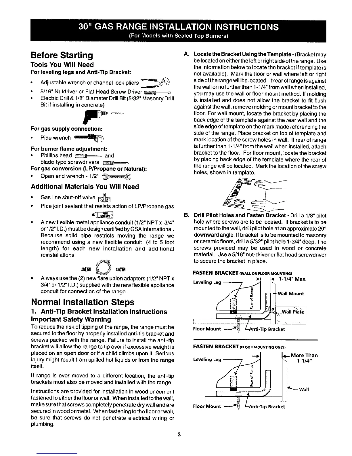
Drill Pilot Holes and Fasten Bracket - Drill a 1/8"pilot
holewhere screwsare to be located. If bracket isto be
mountedtothewall, drill pilot hole atan approximate20°
downwardangle. If bracket isto be mountedto masonry
or ceramic floors,drill a 5/32" pilot hole 1-3/4" deep. The
screws provided may be used in wood or concrete
material. Usea5/16" nut-driver orflat head screwdriver
to secure the bracket in place.
FASTEN BRACKET (WALLOhFLOORMOUNTING)
--_r i<--1-1/4" Max
Leveling Leg --
Wall Mount
Wall Plate
I J
Floor Mount _! p Bracket
FASTEN BRACKET (FLOOR MOUNTING ONLY)
--'-_l - More Than
Leveling Leg -- 1-1/4"
Floor Mount v p Bracket