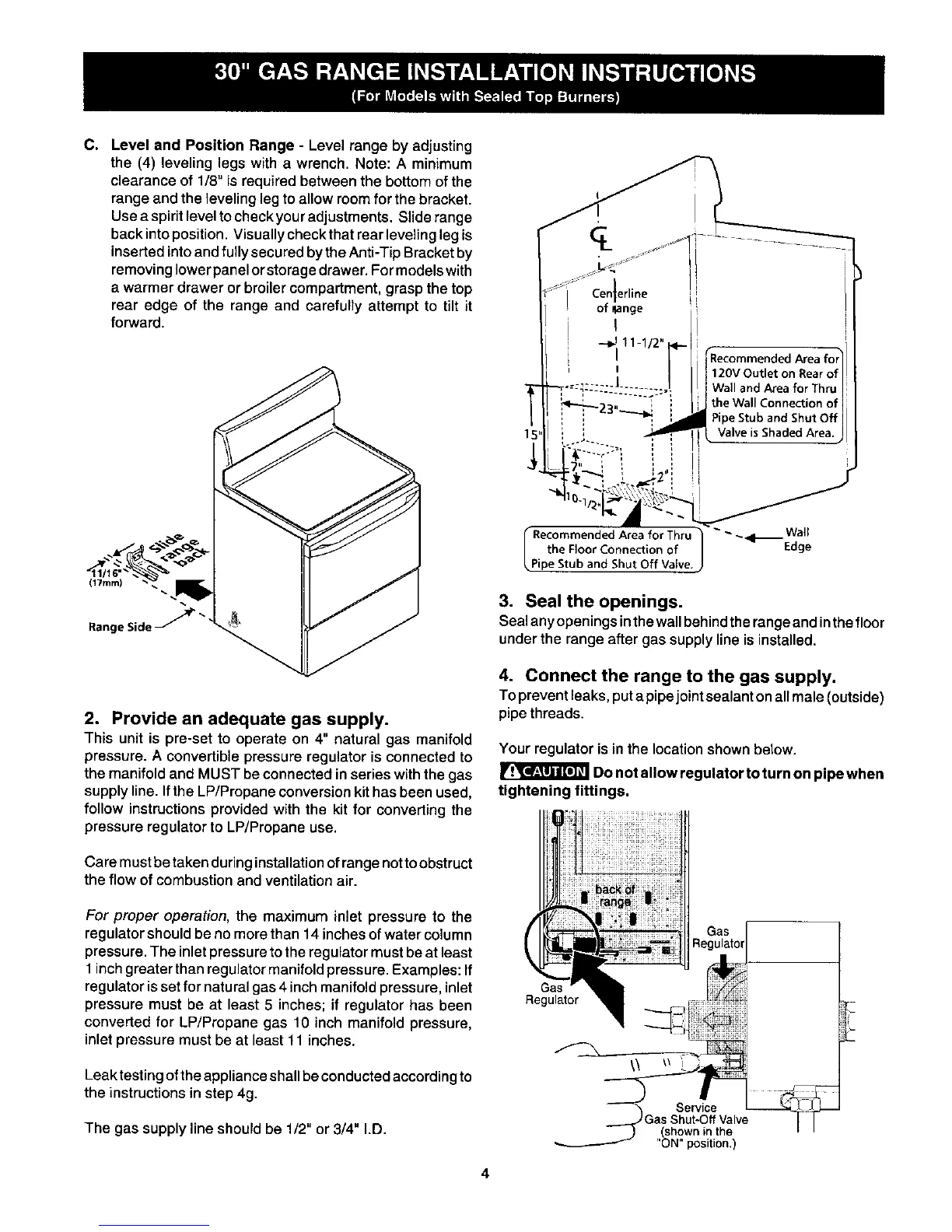
C. Level and Position Range - Level range by adjusting
the (4) leveling legs with a wrench. Note: A minimum
clearance of 1/8" is requiredbetween the bottomofthe
range and theleveling legto allowroomfor the bracket.
Usea spiritlevel to checkyouradjustments. Sliderange
backintoposition.Visuallycheck thatrear levelingleg is
insertedintoand fully secured bythe Anti-TipBracketby
removing lowerpanelorstorage drawer. Formodelswith
a warmer drawer or broiler compartment,graspthe top
rear edge of the range and carefully attempt to tilt it
forward.
(17ram)
Range Side _"
2. Provide an adequate gas supply.
This unit is pre-set to operate on 4" natural gas manifold
pressure. A convertible pressure regulator is connected to
the manifold and MUST be connected in series with the gas
supply line. If the LP/Propane conversion kit has been used,
follow instructions provided with the kit for converting the
pressure regulator to LP/Propane use.
Care mustbe taken during installationof rangenottoobstruct
the flow of combustion and ventilation air.
For proper operation, the maximum inlet pressure to the
regulator should be no more than 14 inches of water column
pressure. The inlet pressure to the regulator must be at least
1 inch greater than regulator manifold pressure. Examples: If
regulator is set for natural gas 4 inch manifold pressure, inlet
pressure must be at least 5 inches; if regulator has been
converted for LP/Propane gas 10 inch manifold pressure,
inlet pressure must be at least 11 inches.
Leaktesting of the appliance shall be conducted according to
the instructions in step 4g.
The gas supply line should be 1/2" or 3/4" I.D.
ige
I
--_111-1/2 ___
r "Recommended Area for]l
I / 120V Outlet on Rear ell!
I ._,.=: ÷-----I ...... , | WallandAreaforThru|
......:?i theWo,,Conno ,,ooo,,
i " "'* ---_ 3_ PipeStubandShutOff|l
. i i._ P , ValveisShadedArea'JI
-J_7" i _ ', ,,:
__ .._.,_ ,, I J
I,..o en0e0,o.,o,, u] ,--W"
the Floor Connection of Edge
Pipe Stub and Shut Off Valve.
3. Seal the openings.
Sealanyopeningsinthe wallbehindthe rangeandinthe floor
underthe range after gas supplyline isinstalled.
4. Connect the range to the gas supply.
To prevent leaks, put a pipejoint sealant on allmale (outside)
pipe threads.
Your regulator is in the location shown below.
Do not allow regulator to turn on pipe when
tightening fittings.