Before Starting
Tools You Will Need
For leveling legs and Anti-Tip Bracket:
Adjustable wrench or channel lock pliers
5/16" Nutdriver or Flat Head Screw Driver _{]==_=
• Electric Drill & 1/8" Diameter Drill Bit (5/32" Masonry Drill
Bit if installing in concrete)
For gas supply connection:
• Pipe wrench
For burner flame adjustment:
Phillipshead _ and
blade-typescrewdrivers
For gas conversion (LP/Propane or Natural):
• Open end wrench- 1/2"
Additional Materials You Will Need
Gas lineshut-oft valve
Pipe joint sealant that resists action of LP/Propane gas
A new flexible metal appliance conduit (1/2" NPT x 3/4"
or 1/2"I.D.) must be designcertified byCSA International.
Because solid pipe restricts moving the range we
recommend using a new flexible conduit (4 to 5 foot
length) for each new installation and additional
reinstallations.
• Always use the (2) new flare union adapters (1/2" NPT x
3/4" or 1/2" I.D.) supplied with the new flexible appliance
conduit for connection of the range.
Normal Installation Steps
1. Anti-Tip Bracket Installation Instructions
Important Safety Warning
To reduce the riskoftipping of the range, the rangemust be
secured to the floorby properly installedanti-tip bracket and
screws packed withthe range. Failure to installthe anti-tip
bracket willallowthe range totipover if excessive weight is
placed on an open door or if a childclimbs upon it. Serious
injury mightresultfrom spilled hot liquidsor from the range
itself.
If range is ever moved to a different location, the anti-tip
brackets must also be moved and installed with the range.
Instructions are provided for installation in wood or cement
fastened to either the floor or wall. When installed to the wall,
make surethat screws completely penetrate dry wall and are
secu red inwood or metal. When fastening tothe floor orwall,
be sure that screws do not penetrate electrical wiring or
plumbing.
A.
a.
3
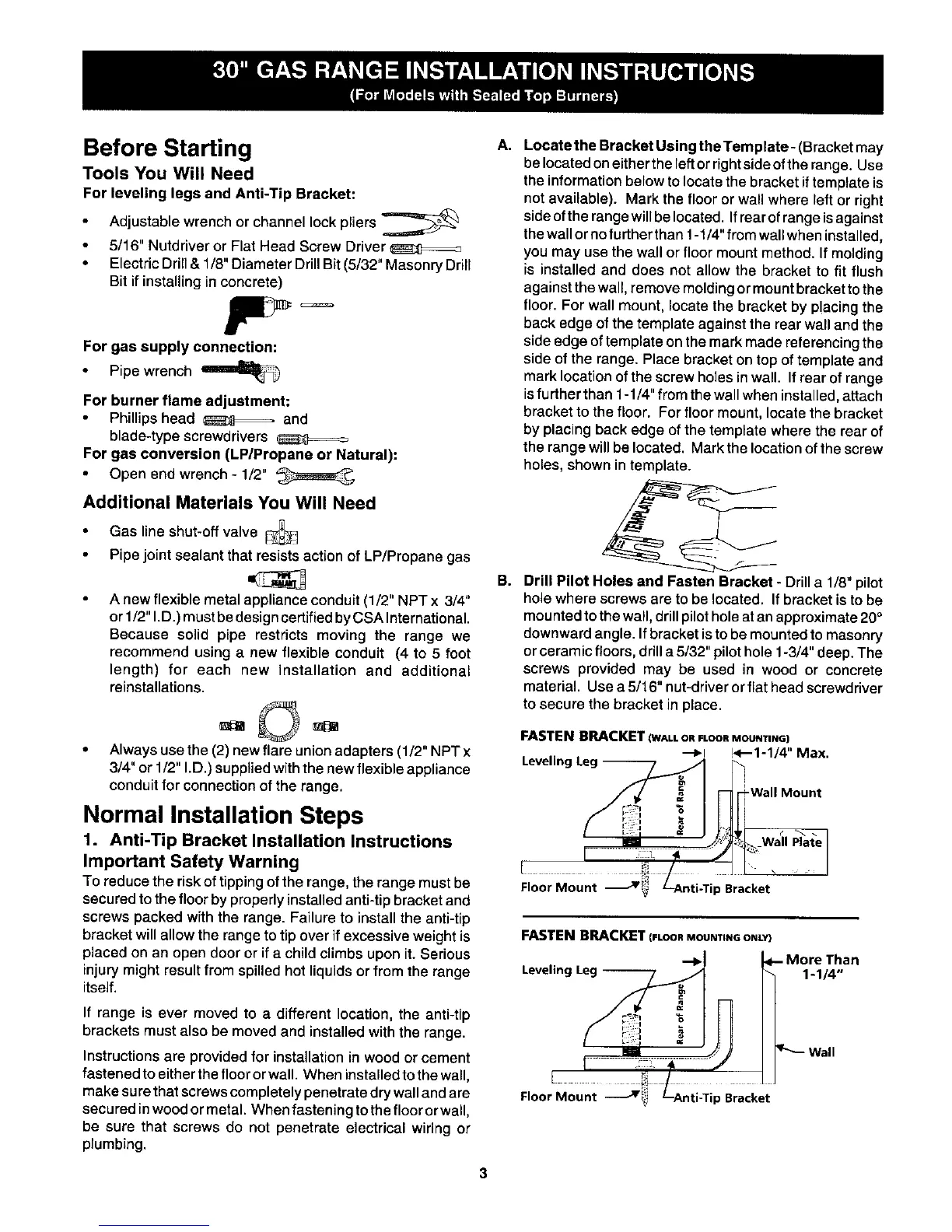
Locate the Bracket Using the Template- (Bracket may
be locatedoneithertheleft orrightsideofthe range. Use
theinformationbelow tolocatethe bracketiftemplate is
not available). Mark the flooror wall where left or right
sideofthe rangewillbelocated, Ifrearofrangeisagainst
thewallornofurtherthan 1-1/4"fromwallwhen installed,
you may use the wall orfloor mount method, If molding
is installedand does not allow the bracket to fit flush
against thewall,remove molding ormountbrackettothe
floor.For wall mount, locate the bracket by p!acing the
back edge of the template againstthe rearwall and the
side edge of template on the mark made referencing the
side of the range. Place bracket on top of template and
mark location of the screw holes in wall. If rear of range
isfurther than 1-1/4" from the wall when installed, attach
bracket to the floor. For floor mount, locate the bracket
by placing back edge of the template where the rear of
the range will be located. Mark the location ofthe screw
holes, shown in template.
Drill Pilot Holes and Fasten Bracket - Drill a 1/8" pilot
holewhere screws are to be located. If bracket is tobe
mounted to the wall, drill pilot hole atan approximate 20°
downward angle. If bracket isto be mounted to masonry
or ceramic floors, drill a 5/32" pilot hole 1-3/4" deep. The
screws provided may be used in wood or concrete
material. Use a 5/16" nut-driver or flat head screwdriver
to secure the bracket in place.
FASTEN BRACKET (WALL OR FLOOR MOUNTING)
--_1 !<--1-1/4" Max.
Leveling Leg --
t
Wall Plate
Floor Mount J p Bracket
FASTENBRACKET(FLOOnMOUNTINGONLY}
Leveling
an
1-1/4 °,
Floor Mount Jii p Bracket