EasyManua.ls Logo

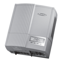
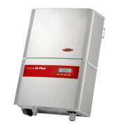
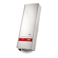
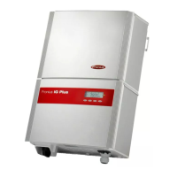
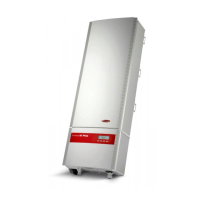
Fronius IG Plus 150 V-3 User Manual

Fronius IG Plus 150 V-3
168 pages
To Next Page IconTo Next Page
Page #1 background imageLoading...
Page #1 background image
42,0426,0062,EA 02/2011
Fronius IG Plus
30 V / 35 V / 50 V / 70 V
100 V / 120 V / 150 V
g
Operating Instructions
Inverter for grid-connected photo-
voltaic systems

Table of Contents

Question and Answer IconNeed help?

Do you have a question about the Fronius IG Plus 150 V-3 and is the answer not in the manual?

Fronius IG Plus 150 V-3 Specifications

General IconGeneral
AC voltage range180-280 V
Protection classIP65
AC Power Output15000 W
Rated Output Power15000 W
Max. apparent AC power15.0 kVA
Frequency Range60 Hz

Summary

Safety Rules

Protection of Persons and Equipment

Galvanic Isolation

Explains the inverter's galvanic isolation for enhanced safety.

Grid Monitoring

Describes how the inverter monitors grid conditions for safe operation.

Choosing the Location

General Location Criteria

Provides general criteria for selecting an installation location.

Indoor Installation Guidelines

Lists specific requirements for indoor installation sites.

Fronius IG Plus Installation

Attaching the Wall Bracket

Step-by-step guide for mounting the wall bracket.

Connecting the Fronius IG Plus to the Public Grid (AC)

AC-Side Terminals

Details connections for single, two, and three-phase inverters.

Solar Module Ground at Positive Pole for Fronius IG Plus

Safety Instructions

Safety warnings for grounding.

Inserting Option Cards

Safety Precautions for Option Cards

Safety warnings when handling option cards.

Data Communication and Solar Net

Solar Net and Data Interface

Explains the Solar Net communication system.

Commissioning

Start-up Operation

Steps for powering on and starting the inverter.

Product Description Fronius IG Plus

Controls and Indicators

Identifies and describes the inverter's controls and indicators.

Display Unit Description

Explains the inverter's display and its functions.

The Setup Menu

Setup Lock Function

Troubleshooting and Maintenance

Status Diagnosis and Troubleshooting

Overview of self-diagnostic system and status codes.

Class 4 Status Codes

Status codes requiring technician intervention.

Class 5 Status Codes

Status codes that may not impair grid feed-in.

Replacing String Fuses

Appendix

Technical Data

Specifications and technical details of the inverter models.

Related product manuals