EasyManua.ls Logo

FS S2800S Series User Manual

Default Icon
45 pages
To Next Page IconTo Next Page
Page #1 background imageLoading...
Page #1 background image
PWR SYS
1
2 4 6 8 10 12 14 16 18 20 22 24 26
PoE
28
2 5 7 9 11 13 15 17 19 21 23 25 27
Link/Act
Link/Act
RESET
S2800S-24T4F-P PoE+
21
43
65
87
109
1211
1413
1615
2019
2221
2423
1817
SFP
RESET
PWR
S2800S-48T4F
2
109
1
43
65
87
1211
1413
1615
1817
2019
2221
2423
2625
2827
3029
3231
3433
3635
3837
4039
4241
4443
4645
4847
49
50
51
52
SFP
Green=1000M Yellow=10/100M On=Link Flashing=ACT
S2800S-24T2F
1 3 5 7 9 11 13 15 17 19 21 23
Link/Act
Link/Act
2PWR 4 6 8 10 12 14 16 18 20 22
RESET
SYS
24
21
43
65
87
109
1211
1413
1615
2019
2221
2423
1817
SFP
25
25
26
26
S2800S-8T2F-P
PoE+
1
Green=1000M
PWR
SYS
1
PoE
100M
1000M
2 3 4 5 6 7 8
9
10
Link/Act
Link/Act RESET
Yellow=10/100M On=Link Flashing=ACT
2 3 4 5 6 7 8
SFP
9 10
S2800S-8T
1 2 3 4 5 6 7 8
RESET
PWR
Green=1000M Yellow=10/100M On=Link Flashing=ACT
SMART MANAGED L2+ BUSINESS SWITCHES
S2800S Series Switches
SMART MANAGED L2+ BUSINESS SWITCHES
SWITCHS D'ENTREPRISE GÉRÉS L2+ INTELLIGENTS
Quick Start Guide
V2.0
Quick-Start Anleitung
Guide de Démarrage Rapide
Question and Answer IconNeed help?

Do you have a question about the FS S2800S Series and is the answer not in the manual?

FS S2800S Series Specifications

General IconGeneral
SeriesS2800S
CategorySwitch
LayerLayer 2+
ModelS2800S Series
Uplink4 x 10GE SFP+
Switching Capacity128 Gbps
Forwarding Rate95.2 Mpps
Power SupplyInternal
Power Consumption30W | 40W
Operating Temperature0°C to 50°C (32°F to 122°F)
Storage Temperature-40°C to 70°C
Operating Humidity10% to 90% non-condensing
Dimensions440mm x 220mm x 44mm
ManagementCLI, SNMP

Summary

Introduction

Hardware Overview

Front Panel Ports

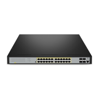
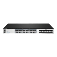
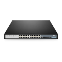
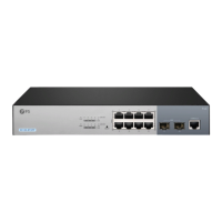
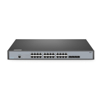
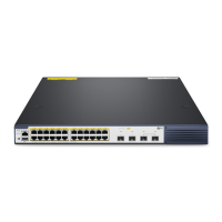
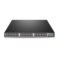
Details RJ45 and SFP ports for various S2800S switch models.

Front Panel Buttons

Describes the function of front panel buttons on different switch models.

Back Panels

Illustrates and labels the connection points on the rear of the switches.

Front Panel LEDs

Explains the meaning of status lights on the front panel of the switches.

Installation Requirements

Site Environment

Specifies optimal conditions for switch installation and operation.

Mounting the Switch

Desk Mounting

Instructions for placing the switch on a flat surface.

Rack Mounting

Steps for securing the switch into a standard equipment rack.

Grounding the Switch

Connecting the Power

Connecting the RJ45 Ports

Connecting the SFP Ports

Configuring the Switch

Configuring the Switch Using the Web-based Interface

Step-by-step guide to setting up the switch via its web interface.

Troubleshooting

1G Port is not Working

Solutions for issues with 1G ports not functioning correctly.

Connecting the Switch Remotely Unsuccessfully

Steps to resolve problems with remote switch access.

The Port is not Working, the LED Indicator is Off

Diagnosing port issues indicated by inactive LEDs.

RJ45 Port Connectivity Issues

Troubleshooting connectivity and data transmission problems on RJ45 ports.

Support and Other Resources

Product Warranty

Compliance Information

FCC Compliance

Details FCC compliance statements and regulations for the device.

CE Compliance

Outlines CE compliance declarations and related directives for the equipment.

Related product manuals