Do you have a question about the FS S5860-20SQ and is the answer not in the manual?
This guide familiarizes users with the switch layout and deployment in a network.
Lists included items like power cord, grounding cable, rubber pads, mounting brackets, and screws.
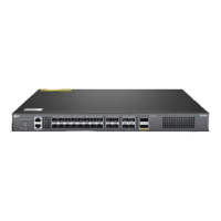
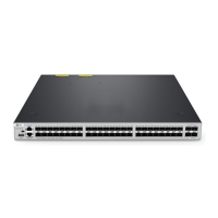
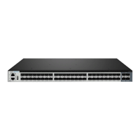
Details SFP+, SFP28, QSFP+, MGMT, CONSOLE, and USB ports on the front panel.
Explains the function of the FUNC button on the front panel.
Identifies grounding point, fan slots, and dual power supplies on the back panel.
Describes the status and meaning of LEDs for system, power, fan, and management ports.
Lists necessary tools, cables, and specifies conditions for operation, ventilation, and humidity.
Instructions for desk mounting using rubber pads and rack mounting using brackets.
Guides on installing the power supply module and connecting the grounding cable.
Details how to connect the AC power cord to the switch and power source.
Explains how to connect fiber optic or DAC cables to SFP+, SFP28, and QSFP+ ports.
Details connecting the console port for serial management and the MGMT port for network management.
Guides on configuring the switch using its web-based interface via the MGMT port.
Explains how to configure the switch using the console port and terminal emulation software.
Addresses power system faults, terminal connection issues, and error codes.
Provides links for downloads, help center, and contact information.
Outlines the warranty terms and return policy for the S5860-20SQ switch.
The S5860-20SQ is a managed L2/L3 enterprise switch designed for robust network deployments. This quick start guide provides a comprehensive overview of the switch's layout, installation procedures, and initial configuration steps, ensuring a smooth integration into your network infrastructure.
The S5860-20SQ switch serves as a central component in enterprise networks, offering advanced Layer 2 and Layer 3 switching capabilities. It is equipped with a variety of ports to support diverse connectivity needs, including SFP+, SFP28, and QSFP+ ports. The SFP+ ports are designed for 1/10G connections, providing flexible options for connecting servers, storage devices, and other network equipment requiring high-speed links. For even higher bandwidth requirements, the SFP28 ports support 10/25G connections, making them suitable for demanding applications such as data center interconnects and high-performance computing. The QSFP+ ports offer versatile connectivity for 40G or 4x 10G connections, enabling aggregation of multiple lower-speed links or direct high-speed uplinks to core network devices.
Beyond its data forwarding capabilities, the switch includes dedicated management interfaces to facilitate easy administration. An out-of-band Ethernet management (MGMT) port allows for remote configuration and monitoring, ensuring that network administrators can manage the device even if the primary data plane is experiencing issues. An RJ45 console port provides serial management access, which is crucial for initial setup, troubleshooting, and direct command-line interface (CLI) operations. Additionally, a USB management port is available for software and configuration backup, as well as offline software upgrades, simplifying maintenance tasks and disaster recovery.
The S5860-20SQ is designed to be a reliable and high-performance solution for enterprise environments, supporting complex network topologies and demanding traffic loads. Its managed capabilities allow for granular control over network traffic, security policies, and quality of service (QoS), ensuring optimal network performance and reliability.
The S5860-20SQ switch is designed for flexible deployment, supporting both desk mounting and rack mounting configurations. For desk mounting, the switch comes with four rubber pads that attach to the bottom, providing stability and protecting surfaces. This option is ideal for smaller deployments or temporary setups where a rack is not available. For more permanent and structured installations, the switch can be securely mounted in a standard 19-inch wide rack, requiring a minimum of 1U height. Mounting brackets and M4 screws are provided for this purpose, ensuring a secure fit within the rack.
Powering the switch involves installing power supply modules into dedicated slots on the back panel. The process is straightforward: a new power module is inserted into the chassis along a guide rail until a click is heard, indicating it is properly seated and in good contact with the power slot. It is important to ensure the power panel is oriented correctly to avoid wrong insertion. The switch supports dual power supplies, enhancing redundancy and reliability. Grounding the switch is a critical safety step, involving connecting one end of a grounding cable to a proper earth ground and securing the grounding lug to the grounding point on the switch's back panel with washers and screws. Once grounded, AC power cords are plugged into the power ports on the back of the switch and connected to an AC power source. A crucial safety warning advises against installing power cables while the power is on.
Connecting network devices to the S5860-20SQ is facilitated by its various port types. For SFP+ and SFP28 ports, users first install the respective transceivers and then connect fiber optic cables. Alternatively, DAC (Direct Attach Copper) cables can be directly connected to SFP+ slots. Similarly, for QSFP+ ports, transceivers are installed, followed by fiber optic cables, or DAC cables can be directly connected. A safety warning highlights the danger of laser beams, advising against looking into the bores of optical modules or fibers without eye protection.
Management connectivity is provided through a console port and an MGMT port. The console port allows for serial management by connecting an RJ45 connector to the switch's console port and a DB9 female connector to the serial port on a computer. This is typically used for initial setup and command-line configuration. For network-based management, the MGMT port is connected to a computer using a standard RJ45 Ethernet cable.
Initial configuration of the switch can be performed via a web-based interface or through the console port. For web-based configuration, the computer's IP address is set within the same subnet as the switch's default management IP (192.168.1.x), and then a web browser is used to access the switch's IP address (http://192.168.1.1) with default credentials (admin/admin). For console-based configuration, terminal simulation software like HyperTerminal is used, with specific parameters set for baud rate, data bits, parity, and stop bits.
The S5860-20SQ incorporates several features to aid in maintenance and troubleshooting, ensuring continuous operation and quick resolution of potential issues. The front panel LEDs provide immediate visual feedback on the switch's operational status, power supply health, fan status, management port activity, and individual port link status.
The STATUS LED indicates the overall system health: off means powered off, solid red indicates a system fault or high temperature, blinking green signifies initialization, solid green means proper operation, and solid yellow indicates the temperature has reached a threshold. The PWR1/PWR2 LEDs monitor the power modules: off if a module is not in position, solid green for proper operation, and solid red for a power fault. The FAN LED indicates fan status: solid green for proper operation and solid red for a fan fault, an incompatible fan model, or missing fans. The MGMT LED shows the status of the management port: off if not connected, green if connected, and blinking green when transmitting or receiving data. Individual port LEDs (SFP+, SFP28, QSFP+) provide link status and activity: off if not connected, solid green if connected at the specified speed, and blinking green when transmitting or receiving data. The ID LED, which can be controlled by CPLD or O&M personnel, helps in identifying the switch remotely.
Troubleshooting guidance is provided for common issues. For power system faults, where indicators are off and fans are not working, the manual suggests checking power cord connections, cabinet power socket connections to power modules, and proper installation of power modules. If the terminal shows no output after power-on, users are advised to check serial port cable connections and the configuration of the serial port on the HyperTerminal software. For error codes displayed on the terminal, the primary recommendation is to confirm that the terminal parameters (e.g., baud rate, data bits) are set correctly.
The FUNC button on the front panel serves as a critical maintenance feature. Pressing and holding the FUNC button for more than five seconds will initiate a restart of the switch after a ten-second delay. This provides a simple way to reboot the device when necessary, without needing to physically cycle power.
The USB management port is a valuable tool for maintenance, allowing for convenient backup of software and configuration files, as well as offline software upgrades. This reduces downtime and simplifies the process of updating the switch's firmware or restoring configurations.
The S5860-20SQ is delivered with dust plugs for its optical ports. Users are advised to keep these dust plugs properly and use them to protect idle optical ports. This practice helps prevent dust and debris from entering the ports, which can degrade optical performance and lead to connection issues, thereby extending the lifespan and reliability of the optical interfaces.
Overall, the S5860-20SQ is designed with ease of use and maintainability in mind, from its clear LED indicators to its robust troubleshooting guidelines and convenient management interfaces.
| Product Series | S5860 Series |
|---|---|
| Switch Type | Managed |
| Port Types | SFP+, SFP28 |
| Power over Ethernet (PoE) | No |
| MAC Address Table | 32K |
| Storage Temperature | -40°C to 70°C (-40°F to 158°F) |
| Operating Humidity | 10% to 90% (non-condensing) |
| Storage Humidity | 5% to 95% (non-condensing) |
| AC Power | 100-240VAC, 50/60Hz |
| Layer | Layer 3 |
| Jumbo Frame | 9216 Bytes |
| CPU | Dual-core |
| Power Supply | AC |
| Operating Temperature | 0°C to 45°C |
| Dimensions | 440 x 200 x 43.6 mm (17.3 x 7.9 x 1.7 inch) |
| Ports | 20 x 10Gb SFP+ and 4 x 25Gb SFP28 |
| Port Configuration | 20 x 10G SFP+ and 4 x 25G SFP28 |