© 2014 Flanders Scientic, Inc.
24
Return to Table of Contents
System Menu
Main Menu System
Function DVI Selection DVI-D
Scopes & Audio Meters DVI Pixel Format Full RGB
Video Component Input COMPONENT
Audio Component Pixel Format YPbPr
Marker 3G Level B Stream 1
System SDI Hue Adjustment Off
Alarm Back Light 35
OSD Back Light Interval On
GPI LED Light On
Color Management Language English
System Status Part Display Off
Support Load Prole Default
Save Prole Prole 1
DVI Selection / DVI Pixel Format
FSI Monitors are equipped with a DVI-I Input, which supports both DVI Digital and DVI Analog sources. To select between
DVI-D (Digital) and DVI-A (Analog) simply toggle this control accordingly. Use DVI Pixel Format to select between Full RGB
(0-255), Limited RGB (16-235), or YCbCr modes.
Component Input / Component Pixel Format
Use Component Input to toggle between Component & Composite Video on the LM-0750W’s or LM-0950W’s shared analog
inputs. Use Component Pixel Format to toggle the Analog Component Video Inputs between YPbPr or RGB mode on all
models.
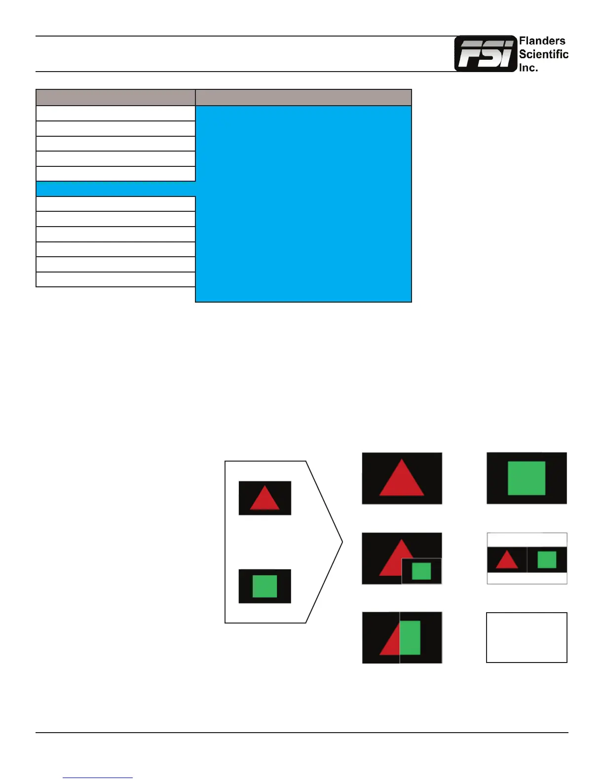
3G Level B
3Gbps SDI (Level B)
Split Screen (Vert or Horiz)
Picture in Picture Picture by Picture
Link B Full ScreenLink A Full Screen
Link A
Link B
Overlay Mode (4:4:4 or 1080p50/60)
4:4:4 SMPTE 425M-B
= 4:2:2 Link A +
0:2:2 Link B
When monitoring a 3Gbps SDI Level B
signal (monitor must be equipped with
3Gbps SDI Inputs) comprised of two
distinct 1.5Gbps HD-SDI signals that
have been muxed together you can
use this 3G Level B selection to select
different monitoring options including:
Stream 1, Stream 2, PAP, PIP, POP,
Vertical Split, Horizontal Split, Overlay
Mode. Please note that Level B 3Gbps
SDI requires that both 1.5Gbps signals
share the same frame rate and resolution
and that Link A and Link B are genlocked.
For signals using SMPTE 425M-B image
format mapping to transport SMPTE
372M formatted Dual Link information
(4:4:4) YCbCr or RGB / 1080p50/60) the
Overlay Mode should be used to view
the combined LinkA and LinkB data as a
single video signal.
 Loading...