•
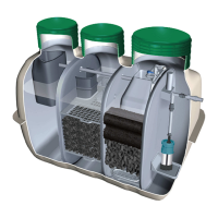
Bottom of the Domed Lid should be
approximately 30mm higher than
ground level so that surface water can
flow away from the system.
•
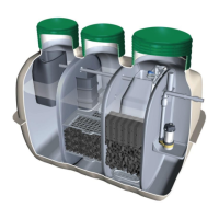
Run the power cable for the pump and
the cable for the float switch through
th
chamber to the blower box.
•
Plug the power cable into
the bottom of the alarm panel.
•
Connect the float switch cable to the
terminal block in the connection box.
•
Pass each cable through the centre of
the Blower box so that it does not touch
the Blower box cover. Interference
•
Apply seal plugs and silicone caulking
the blower box from corrosion.
*
•
Adjust and lock the height of the float
switch so that the switch is triggered as
•
Apply silicone caulking at tank wall and
•
are NOT exposed above the
be protected from UV sunlight.
•
paint/spray coating on the exposed
riser or add extra soil to completely
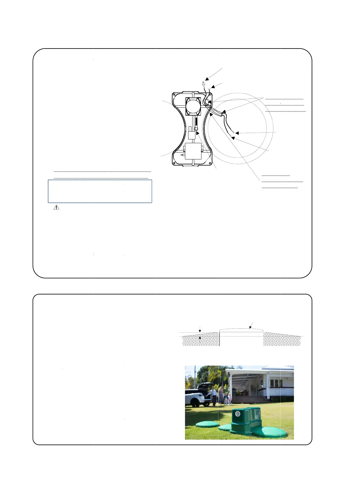
Bottom of the Domed Lid should be
approximately 30mm higher than
ground level so that surface water can
flow away from the system.
Run the power cable for the pump and
the cable for the float switch through
chamber to the blower box.
Plug the power cable into
the bottom of the alarm panel.
Connect the float switch cable to the
terminal block in the connection box.
Pass each cable through the centre of
the Blower box so that it does not touch
the Blower box cover. Interference
Apply seal plugs and silicone caulking
This is very important as it
the blower box from corrosion.
Caution
Adjust and lock the height of the float
switch so that the switch is triggered as
Apply silicone caulking at tank wall and
ompletely cover the riser and tank
are NOT exposed above the
The FRP material needs to
be protected from UV sunlight.
ackfilled ground level will be
paint/spray coating on the exposed
riser or add extra soil to completely
Bottom of the Domed Lid should be
approximately 30mm higher than
ground level so that surface water can
flow away from the system.
Run the power cable for the pump and
the cable for the float switch through
chamber to the blower box.
Plug the power cable into
the bottom of the alarm panel.
Connect the float switch cable to the
terminal block in the connection box.
Pass each cable through the centre of
the Blower box so that it does not touch
the Blower box cover. Interference
Apply seal plugs and silicone caulking
This is very important as it
the blower box from corrosion.
Adjust and lock the height of the float
switch so that the switch is triggered as
Apply silicone caulking at tank wall and
ompletely cover the riser and tank
are NOT exposed above the
The FRP material needs to
be protected from UV sunlight.
ackfilled ground level will be
paint/spray coating on the exposed
riser or add extra soil to completely
Bottom of the Domed Lid should be
approximately 30mm higher than
the
ground level so that surface water can
Run the power cable for the pump and
the cable for the float switch through
the bottom of the alarm panel.
Connect the float switch cable to the
terminal block in the connection box.
Pass each cable through the centre of
the Blower box so that it does not touch
the Blower box cover. Interference
Apply seal plugs and silicone caulking
.
This is very important as it
the blower box from corrosion.
Adjust and lock the height of the float
switch so that the switch is triggered as
Apply silicone caulking at tank wall and
ompletely cover the riser and tank
are NOT exposed above the
The FRP material needs to
be protected from UV sunlight.
ackfilled ground level will be
paint/spray coating on the exposed
riser or add extra soil to completely
6
Ground
Level
the Blower box so that it does not touch
switch so that the switch is triggered as
Connect the
Riser
Connect to the terminal block in the
rubber
GOOD
tom of the
.
Connect to the terminal block in the
and
Connect to the terminal block in the
 Loading...