Do you have a question about the FujiFilm RYB500S3-VBC and is the answer not in the manual?
Indicates severe personal injury or death risk if precautions aren't taken.
Indicates personal injury or property damage risk if precautions aren't taken.
Details contents of the warning label shown in Fig. B.
Lists documents included in the package of each device.
Shows the type designations of products covered in this manual.
Provides a general overview of the FALDIC-β Series AC servo system.
Details the appearance and specifications of the servomotor.
Details the appearance and specifications of the servo amplifier.
Explains the coding system for product type designations.
Describes the damping control function for suppressing mechanical vibrations.
Highlights features for high performance and precision, like 1ms positioning.
Details the compact body and side-by-side installation capability.
Explains the new auto-tuning function and parameter design for ease of use.
Notes conformance to international standards like UL, cUL, and CE marks.
Illustrates the physical appearance of the servomotor and its parts.
Explains how to read the servomotor's model and serial number.
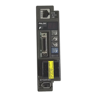
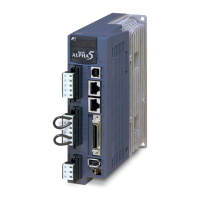
Illustrates the physical appearance of the servo amplifier and its components.
Explains how to read the servo amplifier's model and specifications.
Provides instructions for installing the servomotor.
Provides instructions for installing the servo amplifier.
Specifies the required conditions for storing the servomotor.
Specifies the required conditions for operating the servomotor.
Illustrates the different flange-mounted methods for servomotor installation.
Advises on proper handling to avoid damage to the servomotor and encoder.
Warns against connecting commercial power directly to the servomotor.
Details allowable radial and thrust loads for servomotors and gear heads.
Instructs on applying grease to the servomotor shaft before gear head assembly.
Details steps for preparing the gear head flange for assembly.
Specifies the storage temperature and humidity for the servo amplifier.
Specifies the operating temperature and humidity for the servo amplifier.
Describes the correct mounting orientation for the servo amplifier.
Provides guidelines for mounting multiple amplifiers side-by-side and heat dissipation.
Lists environments unsuitable for servo amplifier operation.
Details the required voltage ranges for servo amplifier power supply.
Shows the general configuration of the FALDIC-β Series system.
Details the wiring connections for the servo amplifier.
Details the wiring connections for the servomotor.
Details the wiring connections for the encoder.
Illustrates the system configuration with a servomotor without a brake.
Illustrates the system configuration with a servomotor with a brake.
Details the voltage and phase requirements for commercial power supply.
Explains the connections for power cables and regenerative resistors.
Lists functions assignable to sequence input/output terminals.
Shows recommended wiring for command pulse with differential output devices.
Shows recommended wiring for command pulse with 24 VDC open collector output devices.
Shows recommended wiring for command pulse with 12 VDC open collector output devices.
Details how to connect the servomotor power cable to the amplifier.
Details encoder wiring connections at the servo amplifier.
Details encoder wiring connections at the servomotor.
Illustrates the standard wiring diagram for 3-phase 200V without brake.
Illustrates the standard wiring diagram for 3-phase 200V with brake.
Illustrates the standard wiring diagram for single-phase 100V without brake.
Illustrates the standard wiring diagram for single-phase 100V with brake.
Outlines the two stages for performing test operations.
Details the steps and checks for the first stage of test operation.
Details the steps and checks for the second stage of test operation.
Describes the display section of the keypad panel.
Lists the functions accessible via the keypad panel modes.
Explains how to display the servo amplifier's status.
Explains how to monitor servomotor speed and I/O status.
Guides on how to edit parameters using the keypad.
Guides on operating the servomotor using the keypad.
Outlines basic inspection procedures for the servo system.
Describes how to back up and initialize memory.
Explains how to diagnose and display faults.
Provides guidance on maintenance and safe discharge.
Provides a flowchart for diagnosing why the servomotor is not rotating.
Provides a flowchart for diagnosing servomotor hunting issues.
Provides a flowchart for diagnosing poor positioning accuracy.
Classifies faults and describes actions upon alarm detection.
Lists fault indications, descriptions, pages, and priority order.
Details various cable types and their specifications.
Lists molded case circuit breakers and earth leakage breakers.
Lists types of electromagnetic contactors.
Explains the function and application of power filters.
Details when and why to use AC reactors.
Provides information on external regenerative resistors.
Lists optional peripheral devices available for the system.
Lists detailed specifications for various servomotor models.
Lists detailed specifications for servo amplifier models.
Shows torque characteristics curves for servomotor and amplifier combinations.
Provides dimensional drawings for servomotors, gear heads, and amplifiers.
Shows speed-torque characteristics for the GYS500DC1-C8B servomotor.
Shows speed-torque characteristics for the GYS101DC1-CB servomotor.
Shows speed-torque characteristics for the GYS201DC1-CA servomotor.
Shows speed-torque characteristics for the GYS401DC1-CA servomotor.
Shows speed-torque characteristics for the GYS751DC1-CA servomotor.
Shows speed-torque characteristics for the GYC101DC1-CA servomotor.
Shows speed-torque characteristics for the GYC201DC1-CA servomotor.
Shows speed-torque characteristics for the GYC401DC1-CA servomotor.
Shows speed-torque characteristics for the GYC751DC1-CA servomotor.
Shows speed-torque characteristics for the GYS500DC1-C8B servomotor.
Shows speed-torque characteristics for the GYS101DC1-C6B servomotor.
Shows speed-torque characteristics for the GYS201DC1-C6B servomotor.
Details the standard shaft extension types, including cylindrical options.
Specifies the standard flange mounting type for servomotors.
Describes the wiring for motor power and encoder cables.
Provides dimensions for GYS series standard motors (50W/100W).
Provides dimensions for GYS series standard motors (200W/400W).
Provides dimensions for GYS series standard motor (750W).
Provides dimensions for GYS series motors with brake (50W/100W).
Provides dimensions for GYS series motors with brake (200W/400W).
Provides dimensions for GYS series motor with brake (750W).
Provides dimensions for GYC series standard motors (100W).
Provides dimensions for GYC series standard motors (200W/400W).
Provides dimensions for GYC series standard motor (750W).
Provides dimensions for GYC series motors with brake (100W).
Provides dimensions for GYC series motors with brake (200W/400W).
Provides dimensions for GYC series motor with brake (750W).
Provides dimensions for GYS series gear heads (50W/100W).
Provides dimensions for GYS series gear heads (200W/400W).
Provides dimensions for GYS series gear head (750W).
Provides dimensions for GYC series gear heads (100W).
Provides dimensions for GYC series gear heads (200W/400W).
Provides dimensions for GYC series gear head (750W).
Shows dimensions for 50W-200W servo amplifiers (100V/200V series).
Shows dimensions for 400W/750W servo amplifiers (200V series).
Provides formulas for calculating the moment of inertia of various shapes.
Provides formulas for calculating load torque for mechanical systems.
Explains various timing charts related to operation and signals.
Lists various optional cables with connectors and their specifications.
Lists various connector kits available for customer-prepared cables.
Lists and describes basic setting parameters from 01 to 09.
Lists and describes system setting parameters from 10 to 39.
Lists and describes control system setting parameters from 40 to 64.
Lists parameters reserved for manufacturer-specific adjustments.
| Communication Interface | RS-485 |
|---|---|
| Shock Resistance | 49 m/s² (5 G) |
| Rated Voltage | 200V |
| Control Method | PWM Control |
| Protection Features | Overcurrent, overvoltage, undervoltage |
| Operating Temperature | 0 to +55°C |
| Vibration Resistance | 5.9 m/s² (0.6G) |