FRESH-AIR INTAKE
(1) Open up the knockout hole for the fresh-air intake, as shown in the
figure. (If using half-concealed installation, open up the top knockout
hole instead.)
POWER
SUPPLY
REMOTE
CONTROL
321
WARNING
1 Before starting work, check that power is not being
supplied to the indoor unit and outdoor unit.
2 Match the terminal board numbers and connection
cord colors with those of the outdoor unit.
Erroneous wiring may cause burning of the electric
parts.
3 Connect the connection cords firmly to the terminal
board. Imperfect installation may cause a fire.
4 Always fasten the outside covering of the connection
cord with the cord clamp. (If the insulator is chafed,
electric leakage may occur.)
5 Always connect the ground wire.
8
10
HOW TO CONNECT WIRING TO THE
TERMINALS
A. For solid core wiring
(1) Cut the wire end with a wire cutter or wire-cutting pliers, then strip
the insulation to about 25 mm (15/16") to expose the solid wire.
(2) Using a screwdriver, remove the terminal screw(s) on the terminal
board.
(3) Using pliers, bend the solid wire to form a loop suitable for the
terminal screw.
(4) Shape the loop wire properly, place it on the ter minal board and
tighten securely with the terminal screw using a screwdriver.
B. For strand wiring
(1) Cut the wire end with a wire cutter or wire-cutting pliers, then strip
the insulation to about 10 mm (3/8") to expose the strand wiring.
(2) Using a screwdriver, remove the terminal screw(s) on the terminal
board.
(3) Using a round terminal fastener or pliers, securely clamp a round
terminal to each stripped wire end.
(4) Position the round terminal wire, and replace and tighten the
terminal screw using a screwdriver.
A. Solid wire
Strip 25 mm (15/16")
Insulation
Loop
B. Strand wire
Strip 10 mm (3/8")
Round
terminal
Wire
Screw with
special washer
Round terminal
Terminal
board
Wire
Screw with
special washer
Round
terminal
Terminal block
4
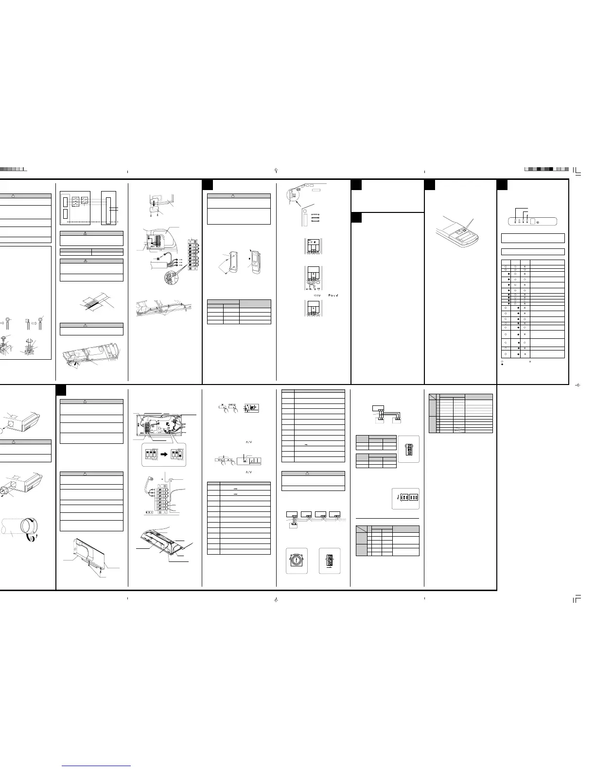
ELECTRICAL WIRING
1. CONNECTION DIAGRAMS
3. INDOOR UNIT
Indoor unit
Control box
Tapping screw
(2) Remove the Cover A and install the Connection cord.
(3) Reattach Cover A. Then fasten the control box back into its original
position using the two tapping screws.
Cover A
Control box
5
REMOTE CONTROL UNIT
INSTALLATION
1. REMOTE CONTROL UNIT HOLDER INSTALLA-
TION
••
••
• Install the remote control unit holder to a wall or pillar with the tapping
screws.
Remote Control Unit
holder fixing
Remote Control
Unit mounting
Remote control
unit holder
Tapping
screws
(small)
1 Set
2 Push
Remote
control unit
2. SWITCHING REMOTE CONTROL UNIT SIGNAL
CODE
• Remote control unit settings
(1) Press the START/STOP button and display only the clock.
(2) Press the MASTER CONTROL button continuously for more than five
seconds to display the current signal code.
(3) Change the signal code with the
button ( ).
(4) Press the MASTER CONTROL button again to return to the clock
display and change the signal code.
Indoor unit
Printed circuit board
6
FINISHING
(1) Install the filter guide.
(2) Install the intake grilles.
(3) Install side covers A and B (if the unit is installed in a half-concealed
orientation, only install side cover A).
(4) Install the air filters.
7
CUSTOMER GUIDANCE
Explain the following to the customer in accordance with the operating
manual:
(1) Starting and stopping method, operation switching, temperature
adjustment, timer, air flow adjustment, and other remote control unit
operations.
(2) Air filter removal and cleaning.
(3) Give the operating manual and installation instruction sheet to the
customer.
TEST RUNNING
••
••
• Perform test operation and check items 1 and 2 below.
••
••
• For the operation method, refer to the operating manual.
••
••
• The outdoor unit may not run, depending on the room temperature.
In this case, the ‘TEST RUN’ signal is received during air conditioner
operation (use a metallic object to short the two metal contacts under
the battery compartment lid and send the ‘TEST RUN’ signal from the
remote control unit).
••
••
• To end test operation, press the remote control unit START/STOP
button.
(When the air conditioner is run by pressing the remote control unit
TEST RUN button, the OPERATION and TIMER lamps will simulta-
neously flash slowly.)
1. INDOOR UNIT
(1) Is operation of each button on the remote control unit normal?
(2) Does each lamp light normally?
(3) Do not air flow direction flap and louvers operate normally?
(4) Is the drain normal?
2. OUTDOOR UNIT
(1) Is there any abnormal noise and vibration during operation?
(2) Will noise, wind, or drain water from the unit disturb the neighbors?
(3) Is there any gas leakage?
9
AN ERROR DISPLAY
1. INDOOR UNIT
Operation can be checked by lighting and flashing of the display section
OPERATION, TIMER and VERTICAL SWING lamps.
Perform judgment in accordance with the following.
For half concealed
installation
Indoor unit
CAUTION
1 When removing the cabinet (iron plate), be careful not
to damage the indoor unit internal parts and surroun-
ding area (outer case).
2 When processing the cabinet (iron plate), be careful
not to injure yourself with burrs, etc.
(2) Fasten the round flange (optional) to the fresh-air intake, as shown in
the figure. (If using half-concealed installation, attach to the top.)
[After completing “2 INDOOR UNIT INSTALLATION”...]
(3) Connect the duct to the round flange.
(4) Seal with a band and vinyl tape, etc. so that air does not leak from the
connection.
Round duct (option parts)
Duct
SWING SWING TIMER
OPERATION
MANUAL
AUTO
VERTICAL SWING lamp (Orange)
TIMER lamp (Green)
OPERATION lamp (Red)
• Test running
When the air conditioner is run by pressing the remote control unit test
run button, the OPERATION, TIMER and VERTICAL SWING lamps
flash slowly at the same time.
• Error
The OPERATION, TIMER and VERTICAL SWING lamps operate as
follows according to the error contents.
Indoor EEPROM abnormal
Outdoor EEPROM abnormal
Indoor room temperature sensor
open
Indoor room temperature sensor
shortcircuited
Indoor heat exchanger temperature
sensor open
Indoor heat exchanger temperature
sensor shortcircuited
Float switch operated
Indoor signal abnormal
Outdoor signal abnormal
Indoor fan abnormal
Outdoor power source connection
abnormal
Outdoor heat exchanger
temperature sensor open
Outdoor heat exchanger
temperature sensor shortcircuited
Outdoor temperature sensor open
Outdoor temperature sensor
shortcircuited
Outdoor discharge pipe temperature
sensor or compressor temperature
sensor open
Outdoor discharge pipe temperature
sensor or compressor temperature
sensor shortcircuited
Outdoor high pressure abnormal
Outdoor discharge pipe temperature
or compressor temperature sensor
abnormal
OPERATION
lamp (RED)
(2 times)
(2 times)
(3 times)
(3 times)
(4 times)
(5 times)
(5 times)
(6 times)
TIMER lamp
(GREEN)
(2 times)
(3 times)
(3 times)
(4 times)
(4 times)
(5 times)
(5 times)
(6 times)
(7 times)
SWING lamp
(ORANGE)
: 0.1s ON/0.1s OFF (flash) : OFF
: 0.5s ON/0.5s OFF (flash)
Jumper wire
JM3
Connect
Disconnect
Connect
Disconnect
Remote control unit
signal code
A (Primary setting)
B
C
D
JM2
Connect
Connect
Disconnect
Disconnect
Short the two metal contacts
under the battery compartment lid.
2. CONNECTION CORD PREPARATION
Power supply cord
or connection cord
Control box
Terminal board
Connection cord
CAUTION
Use care not to mistake the power supply cord and
connection wires when installing.
(1) Remove the two tapping screws and pull the control box downward.
Confirm the setting of the remote control unit signal code and the printed
circuit board setting.
If these are not confirmed, the remote control unit cannot be used to
operate for the air conditioner.
Error contents
30 mm (1-3/16")
40 mm or more
(1-9/16")
For earth
(5) Attach the connection cord and cable clips. Make sure that they are
positioned so that they will not interfere with opening and closing of
the intake grille or with removal and installation of the air filters.
CAUTION
1 Check that the indoor unit correctly receives the
signal from the remote control unit, then install the
remote control unit holder.
2 Select the remote control unit holder selection site by
paying careful attention to the following:
Avoid places in direct sunlight.
Select a place that will not be affected by the heat from
a stove, etc.
(4) Use lock nuts to secure the conduit tube.
Cable clip
Connection cord
Conduit
Lock nut
11
WIRED REMOTE CONTROL
UNIT SETTING (OPTIONAL)
RED
WHITE
BLACK
REMOTE
CONTROL
POWER
SUPPLY
123123
BEFORE INSTALL WIRED REMOTE CONTROL UNIT
••
••
• The wired remote control unit is an option. It isn't included in main body
of air-conditioner.
••
••
• When you use wired remote control unit, some functions may not be
used.
••
••
• please use the recommended wired remote control unit.
(Before installing, Please read the FEATURES AND FUNCTIONS sec-
tion of OPERATING MANUAL to confirm the concerned contents.)
CAUTION
1 Before installing, be sure to disconnect all power sup-
ply.
2 Don't touch the heat exchanger.
3 During installing or removing operation, be sure not to
have wire catched by parts or draw it hard. Or it may
result troubles to the air-conditioner.
4 Avoid place in direct sunlight.
5 Select place that will not be affected by the heat from a
stove, etc.
6 Insure the length of wire is not over the recommended
maximum length.
7 Before setting up the wired remote control unit, please
confirm whether air-conditioner can receive the sig-
nal.
Remove the two screws on the bottom and then remove control box A.
••
••
• To use the optional wired remote control, set up the wiring as shown in
the diagram below.
••
••
• Use the clamps to fasten the remote control wire in three locations.
••
••
• Set up the wiring so that the remote control wire passes under the
capacitor and the plastic.
••
••
• Change the setting for the electrical circuits.
Switch 4 (SW4) on the printed circuit board inside the electric compo-
nent box must be set as follows.
Attach the remote control wire and cable clips.
Do not group the connection cord and remote control wire together.
Earth screw
Control box
Control box A
Screw
RED
WHITE
REMOTE
CONTROL
BLACK
POWER
SUPPLY
231 231
Clamp
Remote control wire
Capacitor, Plastic
Clamp
Clamp
Control box
Terminal board
Cable clip
Cable clip
Connection cord
Remote control wire
Wires
CAUTION
1 Be sure to refer the above diagram and do correct field
wiring.
Wrong wiring causes malfunction of the unit.
2 Check local electrical codes and also any specific
wiring instructions or limitation.
CAUTION
1 When the optional wired remote control is used, please
refer to the wired remote control manual supplied with
the wired remote control.
2 When the unit is set for the optional wired remote con-
trol, the wireless remote control cannot be used.
3 When the unit is set for the optional wired remote con-
trol, MANUAL/AUTO switch on the indoor unit cannot
be used.
4 When the unit is set for the optional wired remote con-
trol, the Display Timer lamp (Green) on the indoor unit
will no longer light.
SW4
SW4 SW4
Wireless remote
control type
Wired remote
control type
(1) Stop the air conditioner operation.
(2) Press the master control button and the fan control button simultane-
ously for 2 seconds or more to start the test run.
Unit number (usually 0)
Error code
(3) Press the start/stop button to stop the test run.
[SELF-DIAGNOSIS]
When the error indication “E:EE” is displayed, follow the following items to
perform the self-diagnosis. “E:EE” indicates an error has occurred.
REMOTE CONTROLLER DISPLAY
(1) Stop the air conditioner operation.
(2) Press the set temperature buttons
simultaneously for
5 seconds or more to start the self-diagnosis.
Refer to the following tables for the description of each error code.
Test run display
(3) Press the set temperature buttons simultaneously for
5 seconds or more to stop the self-diagnosis.
Ex. Self-diagnosis
Error code Error contents
Communication error
(indoor unit
remote controller)
Communication error
(indoor unit outdoor unit)
Room temperature sensor open
Room temperature sensor short-circuited
Indoor heat exchanger temperature sensor open
Indoor heat exchanger temperature sensor short-
circuited
Outdoor heat exchanger temperature sensor
Power source connection error
Float switch operated
Outdoor temperature sensor
Discharge pipe temperature sensor
Model abnormal
Indoor fan abnormal
00
01
02
03
04
05
06
08
09
0A
0c
11
12
TEST RUN
Error code Error contents
Outdoor signal abnormal
Excessive outdoor pressure (permanent stop)
Compressor temperature sensor
Pressure switch error
IPM error
CT error
Active filter module (AFM) error
Compressor does not operate
Outdoor unit fan error
Communication error
(inverter multicontroller)
2 way valve sensor error
Expansion valve error
Connection indoor unit error
13
14
15
16
17
18
19
1A
1b
1c
1d
1E
1F
Indoor unit No. 0 Indoor unit No. 1 Indoor unit No. 2 Indoor unit No. 3
Remote
controller
wire
Remote
controller
(2) Rotary switch setting (indoor unit)
Set the unit number of each indoor unit using the rotary switch on the
indoor unit circuit board.
The rotary switch is normally set to 0.
(3) DIP switch setting (remote controller)
Change DIP switch 1 No. 3 on the remote controller from OFF to ON.
Indoor unit
Rotary Switch
Remote controller
DIP Switch 1
2. DUAL REMOTE CONTROLLERS (OPTIONAL)
Two separate remote controllers can be used to operate the indoor units.
(1) Wiring method (indoor unit to remote controller)
(2) DIP switch setting (remote controller)
Set the remote controller DIP switch 1 No. 1 and 2 according to the
following table.
Number of
remote
controllers
Master unit
1 (Normal)
2 (Dual)
ON
OFF
OFF
OFF
DIP-SW 1 No. 1
DIP-SW 1 No. 2
Remote controller
DIP Switch 1
Number of
remote
controllers
Slave unit
1 (Normal)
2 (Dual)
–
ON
–
ON
DIP-SW 1 No. 1
DIP-SW 1 No. 2
SW3
1 2 3 1 2 3 1 2 3
1 2 3
1 2 3
1. GROUP CONTROL SYSTEM
A number of indoor units can be operated at the same time using a single
remote controller.
(1) Wiring method (indoor unit to remote controller)
SPECIAL INSTALLATION METHODS
CAUTION
1 When setting the rotary switch and DIP switches, do
not touch any other parts on the circuit board directly
with your bare hands.
2 Be sure to turn off the main power.
Remote
controller
wire
Indoor unit
Master
unit
Slave
unit
Remote
controller
PART NO. 9364488028
NO.
SW state
Detail
OFF ON
1 Invalidity Validity
★
Auto restart setting
2 ——
★
Temperature correction
3 ——
★
setting
1 Wireless
★
Wired Remote controller setting
2 —
★
—
Air flow setting
3 —
★
—
DIP-Switch 1
● Indoor unit
● Remote controller
[DIP-SWITCH SETTING]
DIP-Switch 4
3. AUTO RESTART
• When the air conditioner power was temporarily turned off by a power
failure etc., it restarts automatically after the power recovers.
(Operated by setting before the power failure)
The auto restart function can be
canceled.
(1) DIP switch setting (indoor unit)
Change the DIP switch (SW1-1)
on the indoor unit circuit board
from ON to OFF. The auto restart
function will be canceled.
Indoor unit
DIP Switch
(★: Factory setting)
ON
★
Multiple units
Cooling only model
★ Validity
Validity
Invalidity
Invalidity
Invalidity
Invalidity
Detail
Dual remote controller setting
Group control setting
Model setting
AUTO changeover setting
Memory Backup setting
THERMO SENSOR button setting
ENERGY SAVE button setting
Horizontal airflow direction and swing button setting
Vertical airflow direction and swing button setting
Cannot be used.
Cannot be used.
No.
1
2
3
4
5
6
1
2
3
4
5
6
OFF
★
★ One unit
★
Heat & cool model
Invalidity
★ Invalidity
★ Validity
★ Validity
★ Validity
★ Validity
★ Fixed at OFF
★ Fixed at OFF
SW state
DIP-
switch 1
DIP-
switch 2
INDOOR
INDOOR UNIT
OUTDOOR UNIT
TERMINAL
DISCON-
NECT
SWITCH
(FIELD
SUPPLY)
Grounding
line
14AWG
(Inter-unit)
Power lines
230/208 V
230/208 V
230/208 V
TERMINAL
Power supply line
Single-phase, 230/208 V
WARNING
Disconnect switch and circuit breaker for over current pro-
tection given in the table below is to be installed between
the indoor unit and the outdoor unit.
15A 240 V - 5A
Disconnect switch
Circuit breaker (or Fuse)
CIRCUIT
BREAKER
OR FUSE
(FIELD
SUPPLY)
9364488028_IM_back.p65 17/11/05, 14:241
 Loading...